Pumping Traps
Condensate Recovery Devices Pumping Traps
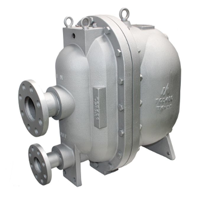
GL81E
Electricity not required / Can be used in explosion prevention areas
Features/Applications
Features
Energy saving
Pumping Traps are able to pressure feed low-pressure condensate to high-pressure condensate recovery lines in higher or remote locations. The incorporation of this product enables the previously unused heat energy of condensate to be recovered and efficiently utilized, thus bringing significant benefits in terms of energy saving.
Electricity not required
Pushes condensate out using the pressure of the motive medium*, therefore can easily be installed in ex-proof areas.
No need for additional power grid for remote installations.
*As well as steam, the motive medium can be compressed air, nitrogen gas, or other such gases.
Easy maintenance
All main connections are on the cover side of the pump. Maintenance access is easy, as it can be performed without detaching the pipes.
Low filling head
The MIYAWAKI pumping traps have a very low filing head, providing good capacity without the need of higher collectors.
Typical applications
● Recovery of low-pressure condensate (in combination with collectors)
● Support the discharge of condensate from heat exchangers operating close to or below 0 barg
● Stall elimination
*Stall is a phenomenon where the steam trap does not work due to a drop in pressure on the device’s primary side and condensate builds up inside the device. Not only does this prevents the discharge of condensate, it also leads to an increased possibility of water hammer or heat exchanger corrosion occurring.
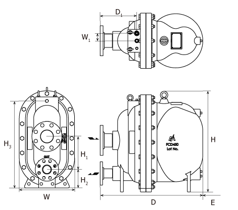
Dimensions/Weight
Dimensions/Weight
| Dimensions (mm) |
Maintenance space |
Weight |
|||||||||||||
| H | H1 | H2 | H3 | D | D1 | W | W1 | E | (kg) | ||||||
|
670
|
220
|
123
|
579
|
680
|
240
|
368
|
50 |
380mm or more | 160 | ||||||
| Dimensions (in) |
Maintenance space |
Weight |
|||||||||||||
| H | H1 | H2 | H3 | D | D1 | W | W1 | E | (lb) | ||||||
|
26.4
|
8.7
|
4.8
|
22.8
|
26.8
|
9.4
|
14.5
|
2.0 |
14.96in or more | 352.8 | ||||||
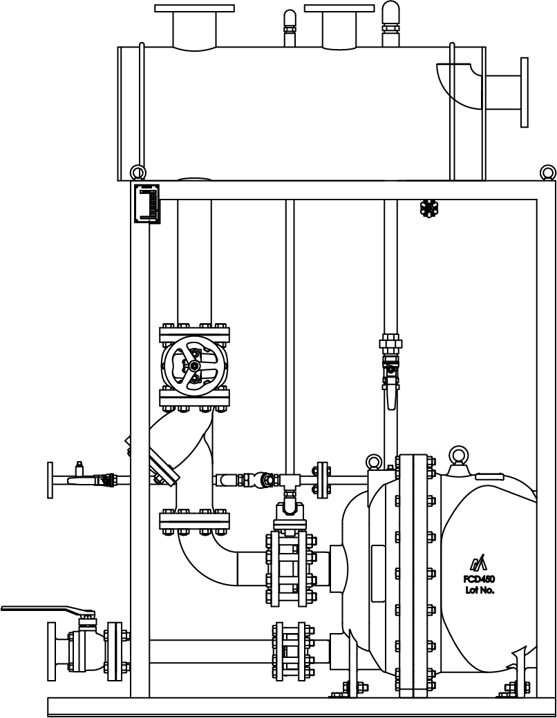
Package unit
Also available is the GL81E-PU package unit model that simplifies attachment and installation.
This compact package includes the requisite piping for pumping trap operation.
Specifications
|
Model |
Connection |
Max. operating pressure |
Max. operating temperature |
Motive medium |
Body material |
|||||
|
Size |
PMO(MPa) | PMO (psig) | TMO(℃) | TMO(℉) | ||||||
|
Condensate inlet |
Condensate outlet |
Motive medium Inlet |
Vent |
|||||||
|
GL81E |
3” (Flanged*1)
|
2” (Flanged*1)
|
1/2” (Screwed)
|
1” (Screwed)
|
1,05 |
152.25 | 185 | 365 |
Steam/ Compressed air/ Nitrogen gas |
Ductile cast iron FCD450 |
●Maximum allowable pressure (PMA): 1,6MPa (232psig)
●Maximum allowable temperature (TMA): 185℃ (365℉)
●Specify the model GL81E-A when ordering. This product is sold in a set that contains the following accessories.
| Inlet-side check valve* | 3” x1 |
| Inlet-side gasket | 3” x2 |
| Inlet-side flange | 3” x1 |
| Inlet-side bolt nuts | 8 sets |
| Body fixings | x2 |
| Outlet-side check valve* | 2” x1 |
| Outlet-side gasket | 2” x2 |
| Outlet-side flange | 2” x1 |
| Outlet-side bolt nuts | 4 sets |
| Bolts, nuts, flat washers for body fixings | 2 sets |
*Please be sure to use standard accessories for the inlet-side and outlet-side check valves.
Flow Capacity Chart
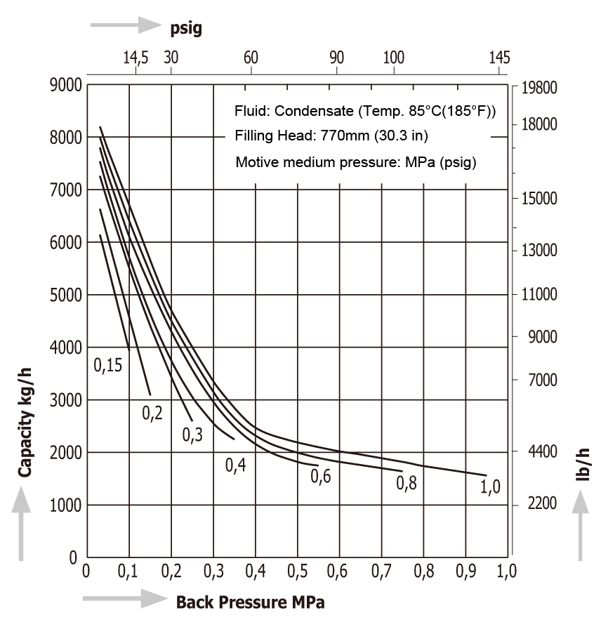
Steam and Air consumption chart for GL81E
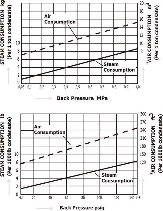
Equivalent consumption of air at 20°C (68°F) under atmospheric pressure,
| Filling Head | FH-factors | |
| mm | in | |
| 150 | 5.9 | 0,66 |
| 270 | 10.6 | 0,75 |
| 370 | 14.5 | 0,82 |
| 570 | 22.4 | 0,92 |
| 770 | 30.3 | 1,00 |
| 970 | 38.2 | 1,01 |
| 1270 | 50.0 | 1,03 |
the capacity of this chart by the "FH-factors".
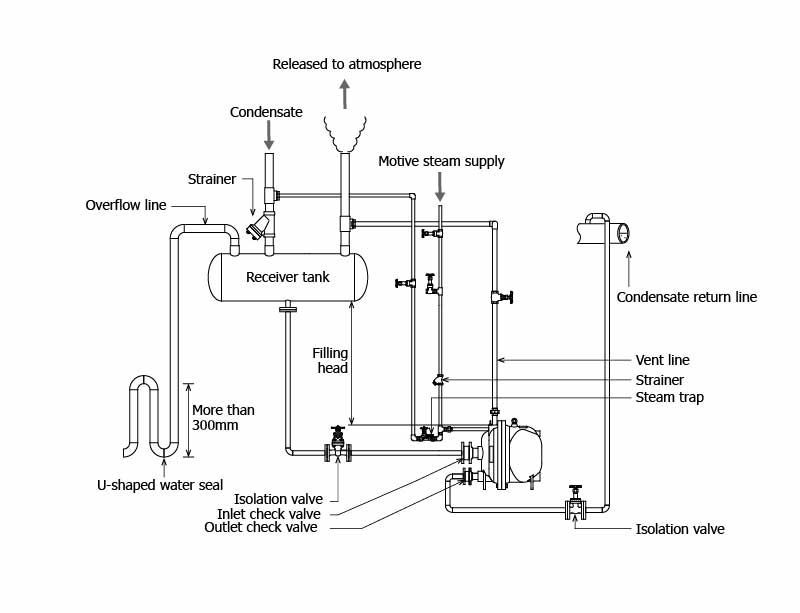
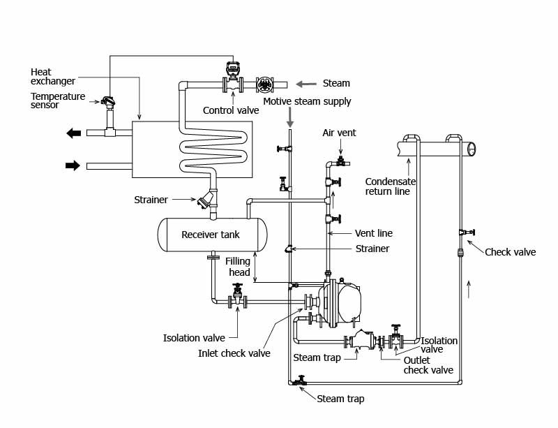
Installation Examples
Open system
Closed system
Download
* Membership registration is required to download the documents.
Features
Energy saving
Pumping Traps are able to pressure feed low-pressure condensate to high-pressure condensate recovery lines in higher or remote locations. The incorporation of this product enables the previously unused heat energy of condensate to be recovered and efficiently utilized, thus bringing significant benefits in terms of energy saving.
Electricity not required
Pushes condensate out using the pressure of the motive medium*, therefore can easily be installed in ex-proof areas.
No need for additional power grid for remote installations.
*As well as steam, the motive medium can be compressed air, nitrogen gas, or other such gases.
Easy maintenance
All main connections are on the cover side of the pump. Maintenance access is easy, as it can be performed without detaching the pipes.
Low filling head
The MIYAWAKI pumping traps have a very low filing head, providing good capacity without the need of higher collectors.
Typical applications
● Recovery of low-pressure condensate (in combination with collectors)
● Support the discharge of condensate from heat exchangers operating close to or below 0 barg
● Stall elimination
*Stall is a phenomenon where the steam trap does not work due to a drop in pressure on the device’s primary side and condensate builds up inside the device. Not only does this prevents the discharge of condensate, it also leads to an increased possibility of water hammer or heat exchanger corrosion occurring.
Dimensions/Weight
| Dimensions (mm) |
Maintenance space |
Weight |
|||||||||||||
| H | H1 | H2 | H3 | D | D1 | W | W1 | E | (kg) | ||||||
|
670
|
220
|
123
|
579
|
680
|
240
|
368
|
50 |
380mm or more | 160 | ||||||
| Dimensions (in) |
Maintenance space |
Weight |
|||||||||||||
| H | H1 | H2 | H3 | D | D1 | W | W1 | E | (lb) | ||||||
|
26.4
|
8.7
|
4.8
|
22.8
|
26.8
|
9.4
|
14.5
|
2.0 |
14.96in or more | 352.8 | ||||||
Package unit
Also available is the GL81E-PU package unit model that simplifies attachment and installation.
This compact package includes the requisite piping for pumping trap operation.
|
Model |
Connection |
Max. operating pressure |
Max. operating temperature |
Motive medium |
Body material |
|||||
|
Size |
PMO(MPa) | PMO (psig) | TMO(℃) | TMO(℉) | ||||||
|
Condensate inlet |
Condensate outlet |
Motive medium Inlet |
Vent |
|||||||
|
GL81E |
3” (Flanged*1)
|
2” (Flanged*1)
|
1/2” (Screwed)
|
1” (Screwed)
|
1,05 |
152.25 | 185 | 365 |
Steam/ Compressed air/ Nitrogen gas |
Ductile cast iron FCD450 |
●Maximum allowable pressure (PMA): 1,6MPa (232psig)
●Maximum allowable temperature (TMA): 185℃ (365℉)
●Specify the model GL81E-A when ordering. This product is sold in a set that contains the following accessories.
| Inlet-side check valve* | 3” x1 |
| Inlet-side gasket | 3” x2 |
| Inlet-side flange | 3” x1 |
| Inlet-side bolt nuts | 8 sets |
| Body fixings | x2 |
| Outlet-side check valve* | 2” x1 |
| Outlet-side gasket | 2” x2 |
| Outlet-side flange | 2” x1 |
| Outlet-side bolt nuts | 4 sets |
| Bolts, nuts, flat washers for body fixings | 2 sets |
*Please be sure to use standard accessories for the inlet-side and outlet-side check valves.
Steam and Air consumption chart for GL81E
Equivalent consumption of air at 20°C (68°F) under atmospheric pressure,
| Filling Head | FH-factors | |
| mm | in | |
| 150 | 5.9 | 0,66 |
| 270 | 10.6 | 0,75 |
| 370 | 14.5 | 0,82 |
| 570 | 22.4 | 0,92 |
| 770 | 30.3 | 1,00 |
| 970 | 38.2 | 1,01 |
| 1270 | 50.0 | 1,03 |
the capacity of this chart by the "FH-factors".
Open system
Closed system
* Membership registration is required to download the documents.