Series G | Ball Float Steam Traps

Steam Traps Series G | Ball Float Steam Traps
G20N
Features/Applications
Features
Suitable for steam process lines
The floating mechanism discharges condensate immediately at saturation temperature, preventing condensate stacking up on the primary side. Ideally installed in applications where condensate logging cannot be accepted.
Time shortening to start up
Automatically discharges initial air and cold condensate. The diaphragm air vent follows the saturation temperature and prevents air and steam locking.
Energy saving design
Achieves high sealing performance even in situations with extremely small amounts of condensate and reduces steam loss thanks to a precision polished float and three point support mechanism.
Condensate recovery
With its high degree of back pressure tolerance, this model supports condensate recovery.
Typical applications
Suitable for use in F&B process equipment, cleaning devices, air conditioning and similar applications.
Dimensions/Weight
Dimensions/Weight
Screwed
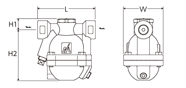
| Size | Dimensions (mm) | Dimensions (in) | Weight | |||||||
| L | H1 | H2 | W | L | H1 | H2 | W | (kg) | (lb) | |
| 1/2” | 120 | 24 | 105 | 82 | 4.7 | 1.0 | 4.1 | 3.2 | 2,5 | 5.5 |
| 3/4” | ||||||||||
| 1” | 107 | 4.2 | 2,6 | 5.7 | ||||||
Flanged
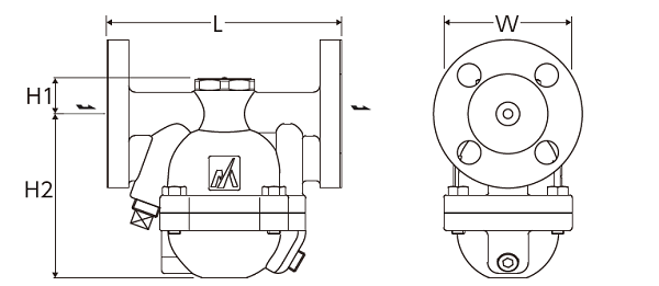
| Size | Flange standards | Dimensions (mm) | Dimensions (in) | Weight | |||||||
| L | H1 | H2 | W | L | H1 | H2 | W | (kg) | (lb) | ||
| 1/2” | JIS(FF,RF) 10K,16K, 20K |
150 | 24 | 105 | 82 | 5.9 | 1.0 | 4.1 | 3.2 | 3,8 | 8.4 |
| ASME/JPI(RF) 150lb |
145 | 5.7 | 3,5 | 7.7 | |||||||
| ASME/JPI(RF) 300lb |
150 | 5.9 | 3,8 | 8.4 | |||||||
| 3/4” | JIS(FF,RF) 10K,16K, 20K |
150 | 5.9 | 4,2 | 9.3 | ||||||
| ASME/JPI(RF) 150lb |
145 | 5.7 | 3,9 | 8.6 | |||||||
| 1” | JIS(FF,RF) 10K,16K, 20K |
160 | 6.3 | 5,3 | 11.7 | ||||||
| ASME/JPI(RF) 150lb |
157 | 6.2 | 4,6 | 10.1 | |||||||
| DN15 | PN25 | 150 | 24 | 105 | 82 | 5.9 | 1.0 | 4.1 | 3.2 | 3,7 | 8.1 |
| DN20 | 4,2 | 9.2 | |||||||||
| DN25 | 160 | 6.3 | 4,8 | 10.6 | |||||||
Specifications
| Model | Connection |
Max. operating pressure |
Max. operating differential pressure |
Max. operating temperature |
Body material | ||||
| Type | Size | PMO (MPa) | PMO (psig) | ⊿PMX (MPa) | ⊿PMX (psig) | TMO (℃) | TMO (℉) | ||
| G20N-3 | Screwed Rc,NPT |
1/2” |
0,3 |
43 | 0,3 | 43 | 220 | 428 |
Ductile cast iron FCD450 |
| 3/4” | |||||||||
| 1” | |||||||||
| G20N-8 | 1/2” | 0,8 | 116 | 0,8 | 116 | ||||
| 3/4” | |||||||||
| 1” | |||||||||
| G20N-21 | 1/2” | 2,1 | 305 | 2,1 | 305 | ||||
| 3/4” | |||||||||
| 1” | |||||||||
| G20N-3F |
Flanged FF,RF |
1/2” | 0,3 | 43 | 0,3 | 43 | |||
| 3/4” | |||||||||
| 1” | |||||||||
| G20N-8F | 1/2” | 0,8 | 116 | 0,8 | 116 | ||||
| 3/4” | |||||||||
| 1” | |||||||||
| G20N-21F | 1/2” | 2,1 | 305 | 2,1 | 305 | ||||
| 3/4” | |||||||||
| 1” | |||||||||
●Maximum allowable pressure (PMA): 2,1MPa (305psig) PMA is the pressure that can be tolerated by pressure-resistant parts (body).
●Maximum allowable temperature (TMA): 220℃ (428℉) TMA is the temperature that can be tolerated by pressure-resistant parts (body).
●Minimum operating differential pressure (⊿PMN): 0,01MPa (1.5psig) ⊿PMN is the minimum operating differential pressure between the trap inlet and outlet.
*Available flange standards: ASME/JPI, DIN, JIS
Discharge Capacity

●The discharge line chart shows the discharge rate for condensate with a temperature 6℃ (11℉) lower than the saturation temperature.
Installation Examples
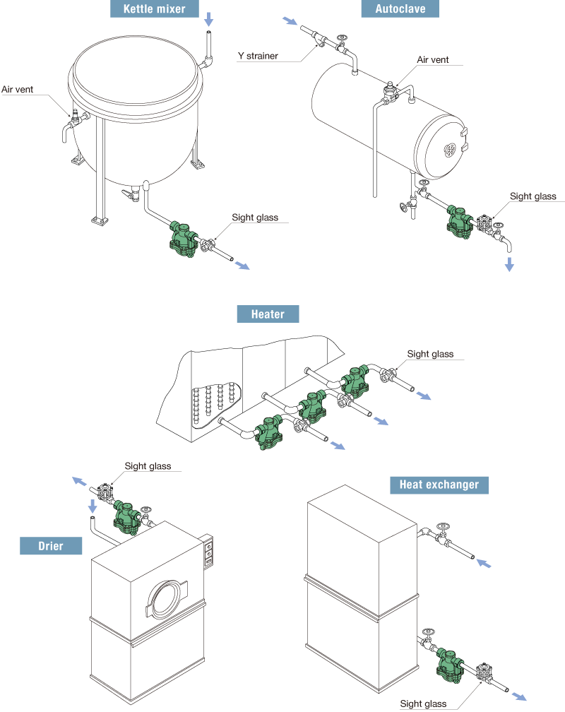
■Related products Models for reference
Y strainer YM1
Sight glass TS1 T3
Air vent AT9N
Download
* Membership registration is required to download the documents.
Features
Suitable for steam process lines
The floating mechanism discharges condensate immediately at saturation temperature, preventing condensate stacking up on the primary side. Ideally installed in applications where condensate logging cannot be accepted.
Time shortening to start up
Automatically discharges initial air and cold condensate. The diaphragm air vent follows the saturation temperature and prevents air and steam locking.
Energy saving design
Achieves high sealing performance even in situations with extremely small amounts of condensate and reduces steam loss thanks to a precision polished float and three point support mechanism.
Condensate recovery
With its high degree of back pressure tolerance, this model supports condensate recovery.
Typical applications
Suitable for use in F&B process equipment, cleaning devices, air conditioning and similar applications.
Dimensions/Weight
Screwed
| Size | Dimensions (mm) | Dimensions (in) | Weight | |||||||
| L | H1 | H2 | W | L | H1 | H2 | W | (kg) | (lb) | |
| 1/2” | 120 | 24 | 105 | 82 | 4.7 | 1.0 | 4.1 | 3.2 | 2,5 | 5.5 |
| 3/4” | ||||||||||
| 1” | 107 | 4.2 | 2,6 | 5.7 | ||||||
Flanged
| Size | Flange standards | Dimensions (mm) | Dimensions (in) | Weight | |||||||
| L | H1 | H2 | W | L | H1 | H2 | W | (kg) | (lb) | ||
| 1/2” | JIS(FF,RF) 10K,16K, 20K |
150 | 24 | 105 | 82 | 5.9 | 1.0 | 4.1 | 3.2 | 3,8 | 8.4 |
| ASME/JPI(RF) 150lb |
145 | 5.7 | 3,5 | 7.7 | |||||||
| ASME/JPI(RF) 300lb |
150 | 5.9 | 3,8 | 8.4 | |||||||
| 3/4” | JIS(FF,RF) 10K,16K, 20K |
150 | 5.9 | 4,2 | 9.3 | ||||||
| ASME/JPI(RF) 150lb |
145 | 5.7 | 3,9 | 8.6 | |||||||
| 1” | JIS(FF,RF) 10K,16K, 20K |
160 | 6.3 | 5,3 | 11.7 | ||||||
| ASME/JPI(RF) 150lb |
157 | 6.2 | 4,6 | 10.1 | |||||||
| DN15 | PN25 | 150 | 24 | 105 | 82 | 5.9 | 1.0 | 4.1 | 3.2 | 3,7 | 8.1 |
| DN20 | 4,2 | 9.2 | |||||||||
| DN25 | 160 | 6.3 | 4,8 | 10.6 | |||||||
| Model | Connection |
Max. operating pressure |
Max. operating differential pressure |
Max. operating temperature |
Body material | ||||
| Type | Size | PMO (MPa) | PMO (psig) | ⊿PMX (MPa) | ⊿PMX (psig) | TMO (℃) | TMO (℉) | ||
| G20N-3 | Screwed Rc,NPT |
1/2” |
0,3 |
43 | 0,3 | 43 | 220 | 428 |
Ductile cast iron FCD450 |
| 3/4” | |||||||||
| 1” | |||||||||
| G20N-8 | 1/2” | 0,8 | 116 | 0,8 | 116 | ||||
| 3/4” | |||||||||
| 1” | |||||||||
| G20N-21 | 1/2” | 2,1 | 305 | 2,1 | 305 | ||||
| 3/4” | |||||||||
| 1” | |||||||||
| G20N-3F |
Flanged FF,RF |
1/2” | 0,3 | 43 | 0,3 | 43 | |||
| 3/4” | |||||||||
| 1” | |||||||||
| G20N-8F | 1/2” | 0,8 | 116 | 0,8 | 116 | ||||
| 3/4” | |||||||||
| 1” | |||||||||
| G20N-21F | 1/2” | 2,1 | 305 | 2,1 | 305 | ||||
| 3/4” | |||||||||
| 1” | |||||||||
●Maximum allowable pressure (PMA): 2,1MPa (305psig) PMA is the pressure that can be tolerated by pressure-resistant parts (body).
●Maximum allowable temperature (TMA): 220℃ (428℉) TMA is the temperature that can be tolerated by pressure-resistant parts (body).
●Minimum operating differential pressure (⊿PMN): 0,01MPa (1.5psig) ⊿PMN is the minimum operating differential pressure between the trap inlet and outlet.
*Available flange standards: ASME/JPI, DIN, JIS
●The discharge line chart shows the discharge rate for condensate with a temperature 6℃ (11℉) lower than the saturation temperature.
■Related products Models for reference
Y strainer YM1
Sight glass TS1 T3
Air vent AT9N
* Membership registration is required to download the documents.