Series G | Ball Float Steam Traps
Steam Traps Series G | Ball Float Steam Traps
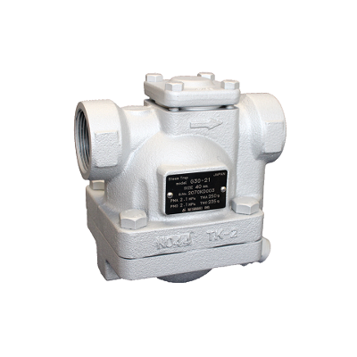
G30
Features/Applications
Features
Suitable for steam process lines
The floating mechanism discharges condensate immediately at saturation temperature, preventing condensate stacking up on the primary side. Ideally installed in applications where condensate logging cannot be accepted.
Quick startup
Automatically discharges initial air and cold condensate. The diaphragm air vent that follows the saturation temperature and prevents air and steam locking.
Minimize Steam Loss, Maximize Maintainability
Thanks to the high-precision polished float and the three-point support mechanism, high sealing performance is maintained even with minimal condensate, and minimizing steam waste. The design, featuring air vent replacement from the top and unitized bottom cover, allows for easy maintenance without removing the steam trap from the steam line.
Eco-friendly by Condensate recovery
With its high degree of back pressure tolerance, this model supports condensate recovery. It reduces energy costs, water expenses, and wastewater treatment costs.
Countermeasure against erosion
Use of stainless steel components at the outlet which is subjected to erosion by the condensate flow.
■Three-point support mechanism
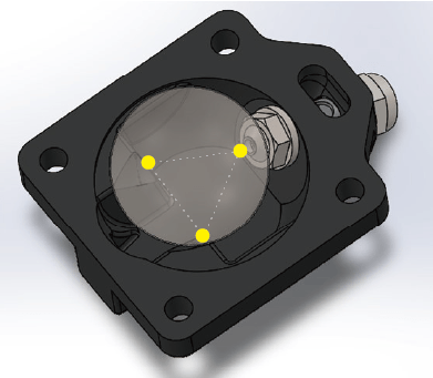 |
Supported by three bases at the bottom, the stability of the float is maintained, |
下部に3点の台座で支えられていることにより、
フロートの安定性を保ち、高シール性と蒸気漏れを最小限にします。
Typical applications
Suitable for use in foodstuff devices, cleaning devices, air conditioning devices, and other such applications.
Dimensions/Weight
Dimensions/Weight
Screwed

| Size | Connections | Dimensions(mm) | Dimensions(in.) | Maintenance space (mm) |
Maintenance space (in.) |
Weight | |||||||||
| L | H1 | H2 | W | L | H1 | H2 | W | E1 | E2 | E1 | E2 | kg | lb | ||
| ¾" |
Screwed (Rc) |
155 | 44 | 125 | 118 | 6.1 | 1.7 | 4.9 | 4.6 | 60 | 70 | 2.4 | 2.8 | 6,7 | 14.8 |
| 1" | 6,5 | 14.3 | |||||||||||||
| 1¼" | 160 | 6.3 | |||||||||||||
| 1½" | 6,3 | 13.9 | |||||||||||||
| ¾" |
Screwed (NPT) |
155 | 44 | 125 | 118 | 6.1 | 1.7 | 4.9 | 4.6 | 60 | 70 | 2.4 | 2.8 | 6,7 | 14.8 |
| 1" | 160 | 6.3 | 6,6 | 14.6 | |||||||||||
| 1¼" | 165 | 6.5 | 6,5 | 14.3 | |||||||||||
| 1½" | 6,3 | 13.9 | |||||||||||||
Flanged

| Size | Connections | Dimensions(mm) | Dimensions(in.) | Maintenance space (mm) |
Maintenance space (in.) |
Weight | |||||||||
| L | H1 | H2 | W | L | H1 | H2 | W | E1 | E2 | E1 | E2 | kg | lb | ||
| 1¼" | JIS(FF,RF) 10K,16K |
260 | 44 | 125 | 118 | 10.2 | 1.7 | 4.9 | 4.6 | 60 | 70 | 2.4 | 2.8 | 10,2 | 22.5 |
| JIS(FF,RF) 20K |
264 | 10.4 | 10,5 | 23.1 | |||||||||||
| ASME/JPI(RF) 150lb |
260 | 10.2 | 9,1 | 20.0 | |||||||||||
| 1½" | JIS(FF,RF) 10K,16K |
260 | 10.2 | 10,4 | 22.9 | ||||||||||
| JIS(FF,RF) 20K |
264 | 10.4 | 10,8 | 23.8 | |||||||||||
| ASME/JPI(RF) 150lb |
260 | 10.2 | 10,0 | 22.0 | |||||||||||
| DN32 | PN25 | 230 | 9.0 | 10,1 | 22.3 | ||||||||||
| DN40 | 10,9 | 24.0 | |||||||||||||
Specifications
| Model | Connection |
Max. Operating
Pressure
|
Max. operating differential
Pressure
|
Max. Operating
Temperature
|
Body Material | ||||
| Type | Size | PMO (MPa) | PMO (psig) | PMX (MPa) | PMX (psig) |
TMO (℃)
|
TMO (℉) | ||
| G30-2 | Screwed Rc,NPT |
¾" |
0,2 | 29 | 0,2 | 29 | 235 | 455 |
Ductile Cast Iron
FCD450
|
|
1” |
|||||||||
|
1¼" |
|||||||||
|
1½" |
|||||||||
| G30-6 |
¾" |
0,6 | 87 | 0,6 | 87 | ||||
|
1” |
|||||||||
|
1¼" |
|||||||||
|
1½" |
|||||||||
| G30-10 |
¾" |
1,0 | 145 | 1,0 | 145 | ||||
|
1” |
|||||||||
|
1¼" |
|||||||||
|
1½" |
|||||||||
| G30-21 |
¾" |
2,1 | 305 | 2,1 | 305 | ||||
|
1” |
|||||||||
|
1¼" |
|||||||||
|
1½" |
|||||||||
| G30-2F | Flanged FF,RF* |
1¼" |
0,2 | 29 | 0,2 | 29 | |||
|
1½" |
|||||||||
| G30-6F |
1¼" |
0,6 | 87 | 0,6 | 87 | ||||
|
1½" |
|||||||||
| G30-10F |
1¼" |
1,0 | 145 | 1,0 | 145 | ||||
|
1½" |
|||||||||
| G30-21F |
1¼" |
2,1 | 305 | 2,1 | 305 | ||||
|
1½" |
|||||||||
●Maximum allowable pressure (PMA): 2,5MPa (363psig) PMA is the pressure that can be tolerated by pressure-resistant parts (body).
●Maximum allowable temperature (TMA): 250℃ (482℉) TMA is the temperature that can be tolerated by pressure-resistant parts (body).
●Maximum operating back pressure (PMOB): 90% of inlet-side pressure
*Available flange standards: JIS 10K,16K,20K, ASME/JPI 150lb, PN25
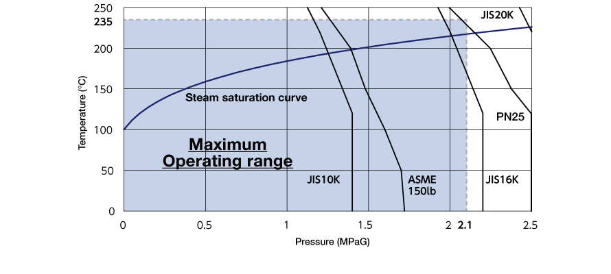
Maximum operating range of pressure and temperature
・PMO: 2.1MPa at 235℃
・TMO: 235℃ at 2.1MPa
Discharge Capacity
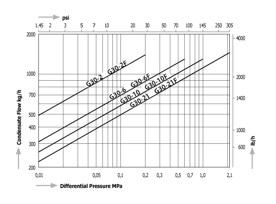
●The discharge line chart shows the discharge rate for condensate with a temperature 6℃ (11℉) lower than the saturation temperature.
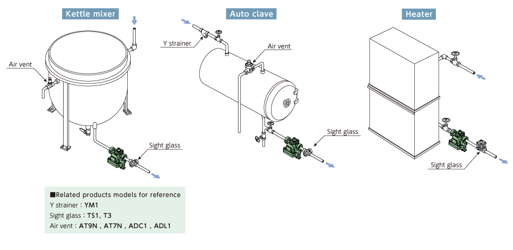
Installation Examples
Download
* Membership registration is required to download the documents.
Features
Suitable for steam process lines
The floating mechanism discharges condensate immediately at saturation temperature, preventing condensate stacking up on the primary side. Ideally installed in applications where condensate logging cannot be accepted.
Quick startup
Automatically discharges initial air and cold condensate. The diaphragm air vent that follows the saturation temperature and prevents air and steam locking.
Minimize Steam Loss, Maximize Maintainability
Thanks to the high-precision polished float and the three-point support mechanism, high sealing performance is maintained even with minimal condensate, and minimizing steam waste. The design, featuring air vent replacement from the top and unitized bottom cover, allows for easy maintenance without removing the steam trap from the steam line.
Eco-friendly by Condensate recovery
With its high degree of back pressure tolerance, this model supports condensate recovery. It reduces energy costs, water expenses, and wastewater treatment costs.
Countermeasure against erosion
Use of stainless steel components at the outlet which is subjected to erosion by the condensate flow.
■Three-point support mechanism
|
Supported by three bases at the bottom, the stability of the float is maintained, |
下部に3点の台座で支えられていることにより、
フロートの安定性を保ち、高シール性と蒸気漏れを最小限にします。
Typical applications
Suitable for use in foodstuff devices, cleaning devices, air conditioning devices, and other such applications.
Dimensions/Weight
Screwed
| Size | Connections | Dimensions(mm) | Dimensions(in.) | Maintenance space (mm) |
Maintenance space (in.) |
Weight | |||||||||
| L | H1 | H2 | W | L | H1 | H2 | W | E1 | E2 | E1 | E2 | kg | lb | ||
| ¾" |
Screwed (Rc) |
155 | 44 | 125 | 118 | 6.1 | 1.7 | 4.9 | 4.6 | 60 | 70 | 2.4 | 2.8 | 6,7 | 14.8 |
| 1" | 6,5 | 14.3 | |||||||||||||
| 1¼" | 160 | 6.3 | |||||||||||||
| 1½" | 6,3 | 13.9 | |||||||||||||
| ¾" |
Screwed (NPT) |
155 | 44 | 125 | 118 | 6.1 | 1.7 | 4.9 | 4.6 | 60 | 70 | 2.4 | 2.8 | 6,7 | 14.8 |
| 1" | 160 | 6.3 | 6,6 | 14.6 | |||||||||||
| 1¼" | 165 | 6.5 | 6,5 | 14.3 | |||||||||||
| 1½" | 6,3 | 13.9 | |||||||||||||
Flanged
| Size | Connections | Dimensions(mm) | Dimensions(in.) | Maintenance space (mm) |
Maintenance space (in.) |
Weight | |||||||||
| L | H1 | H2 | W | L | H1 | H2 | W | E1 | E2 | E1 | E2 | kg | lb | ||
| 1¼" | JIS(FF,RF) 10K,16K |
260 | 44 | 125 | 118 | 10.2 | 1.7 | 4.9 | 4.6 | 60 | 70 | 2.4 | 2.8 | 10,2 | 22.5 |
| JIS(FF,RF) 20K |
264 | 10.4 | 10,5 | 23.1 | |||||||||||
| ASME/JPI(RF) 150lb |
260 | 10.2 | 9,1 | 20.0 | |||||||||||
| 1½" | JIS(FF,RF) 10K,16K |
260 | 10.2 | 10,4 | 22.9 | ||||||||||
| JIS(FF,RF) 20K |
264 | 10.4 | 10,8 | 23.8 | |||||||||||
| ASME/JPI(RF) 150lb |
260 | 10.2 | 10,0 | 22.0 | |||||||||||
| DN32 | PN25 | 230 | 9.0 | 10,1 | 22.3 | ||||||||||
| DN40 | 10,9 | 24.0 | |||||||||||||
| Model | Connection |
Max. Operating
Pressure
|
Max. operating differential
Pressure
|
Max. Operating
Temperature
|
Body Material | ||||
| Type | Size | PMO (MPa) | PMO (psig) | PMX (MPa) | PMX (psig) |
TMO (℃)
|
TMO (℉) | ||
| G30-2 | Screwed Rc,NPT |
¾" |
0,2 | 29 | 0,2 | 29 | 235 | 455 |
Ductile Cast Iron
FCD450
|
|
1” |
|||||||||
|
1¼" |
|||||||||
|
1½" |
|||||||||
| G30-6 |
¾" |
0,6 | 87 | 0,6 | 87 | ||||
|
1” |
|||||||||
|
1¼" |
|||||||||
|
1½" |
|||||||||
| G30-10 |
¾" |
1,0 | 145 | 1,0 | 145 | ||||
|
1” |
|||||||||
|
1¼" |
|||||||||
|
1½" |
|||||||||
| G30-21 |
¾" |
2,1 | 305 | 2,1 | 305 | ||||
|
1” |
|||||||||
|
1¼" |
|||||||||
|
1½" |
|||||||||
| G30-2F | Flanged FF,RF* |
1¼" |
0,2 | 29 | 0,2 | 29 | |||
|
1½" |
|||||||||
| G30-6F |
1¼" |
0,6 | 87 | 0,6 | 87 | ||||
|
1½" |
|||||||||
| G30-10F |
1¼" |
1,0 | 145 | 1,0 | 145 | ||||
|
1½" |
|||||||||
| G30-21F |
1¼" |
2,1 | 305 | 2,1 | 305 | ||||
|
1½" |
|||||||||
●Maximum allowable pressure (PMA): 2,5MPa (363psig) PMA is the pressure that can be tolerated by pressure-resistant parts (body).
●Maximum allowable temperature (TMA): 250℃ (482℉) TMA is the temperature that can be tolerated by pressure-resistant parts (body).
●Maximum operating back pressure (PMOB): 90% of inlet-side pressure
*Available flange standards: JIS 10K,16K,20K, ASME/JPI 150lb, PN25
Maximum operating range of pressure and temperature
・PMO: 2.1MPa at 235℃
・TMO: 235℃ at 2.1MPa
●The discharge line chart shows the discharge rate for condensate with a temperature 6℃ (11℉) lower than the saturation temperature.
* Membership registration is required to download the documents.