Series G | Ball Float Steam Traps
Steam Traps Series G | Ball Float Steam Traps
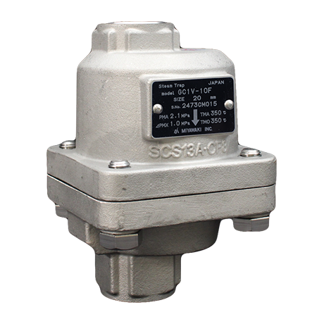
GC1V
Features/Applications
Features
No condensate logging on primary side (continuous discharge float system with self-adjusting orifice)
The floating mechanism discharges condensate immediately at saturation temperature, preventing condensate stacking up on the primary side. Ideally installed in applications where condensate logging cannot be accepted.
Outstanding sealing performance
Achieves high sealing performance and reduces steam loss due to a precision polished float. The float is specially manufactured to comply with the maximum requirements for shape precision and surface tolerance. In combination with the specifically lapped valve, MIYAWAKI provides one of the tightest free floating valve designs in the market.
Auto blow-off system (built-in bimetal)
Automatically discharges initial air and cold condensate.
Compact design
The lever free design consists of less components, therefore reduces potentially defective parts and related maintenance and inspection efforts.
Stainless steel
With the exception of the bimetal, all components are made from corrosion-resistance stainless steel providing superb durability even in contact with aggressive additions in steam.
Typical applications
Suitable for steam main lines, steam tracing, and other such applications.
Dimensions/Weight
Dimensions/Weight
Screwed
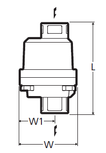
| Size | Dimensions (mm) | Dimensions (in) | Weight | |||||
| L | W | W1 | L | W | W1 | (kg) | (lb) | |
| 1/2” | 127 | 86 | 53 | 5.0 | 3.4 | 2.09 | 1,8 | 4.0 |
| 3/4” | 136 | 5.4 | 1,9 | 4.2 | ||||
| 1” | 140 | 51 | 5.5 | 2.01 | 2,0 | 4.4 | ||
Flanged
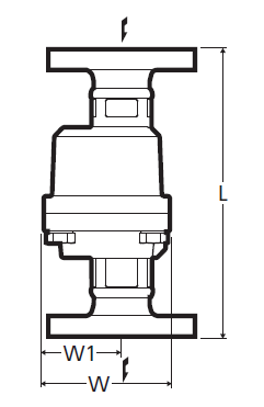
| Size | Dimensions (mm) | Dimensions (in) | Weight (kg) | Weight (lb) | ||||||||||||
| L | W | W1 | L | W | W1 | ASME/JPI (RF) | DIN | JIS (FF) | JIS (RF) | ASME/JPI (RF) | DIN | JIS (FF) | JIS (RF) | |||
| 150lb | 300lb | PN40 | 10K,16K | 20K | 150lb | 300lb | PN40 | 10K,16K | 20K | |||||||
| 1/2" | 175 | 86 | 53 | 6.9 | 3.4 | 2.09 | 2,9 | 3,3 | 3,3 | 3,3 | 3,5 | 6.4 | 7.3 | 7.3 | 7.3 | 7.7 |
| 3/4" | 195 | 7.7 | 3,5 | 4,5 | 4,5 | 3,8 | 4,0 | 7.7 | 9.9 | 9.9 | 8.4 | 8.8 | ||||
| 1" | 215 | 8.5 | 4,2 | 5,3 | 5,3 | 5,0 | 5,3 | 9.2 | 11.7 | 11.7 | 11.0 | 11.7 | ||||
Socket Weld
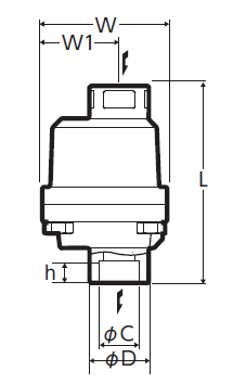
| Size | Dimensions (mm) | Dimensions (in) | Weight | |||||||||||
| L | W | W1 | D | C | h | L | W | W1 | D | C | h | (kg) | (lb) | |
| 1/2” | 127 | 86 | 53 | 36 | 22,2 | 15 | 5.0 | 3.4 | 2.1 | 1.4 | 0.9 | 0.6 | 1,8 | 4.0 |
| 3/4” | 136 | 41 | 27,7 | 5.4 | 1.6 | 1.1 | 1,9 | 4.2 | ||||||
| 1” | 140 | 51 | 50 | 34,5 | 5.5 | 2.0 | 2.0 | 1.4 |
2,0 |
4.4 | ||||
Specifications
| Model | Connection |
Max. operating pressure |
Max. operating differential pressure |
Max. operating temperature |
Body material |
||||
| Type | Size |
PMO (MPa) |
PMO (psig) |
⊿PMX (MPa) |
⊿PMX (psig) |
TMO (℃) |
TMO (℉) |
||
| GC1V-10 | Screwed Rc,NPT |
1/2” | 1,0 | 145 | 1,0 | 145 | 350 | 662 |
Stainless cast steel SCS13A/CF8 |
| 3/4” | |||||||||
| 1” | |||||||||
| GC1V-16 | 1/2” | 1,6 | 230 | 1,6 | 230 | ||||
| 3/4” | |||||||||
| 1” | |||||||||
| GC1V-21 | 1/2” | 2,1 | 305 | 2,1 | 305 | ||||
| 3/4” | |||||||||
| 1” | |||||||||
| GC1V-10F |
Flanged FF,RF |
1/2” | 1,0 | 145 | 1,0 | 145 | |||
| 3/4” | |||||||||
| 1” | |||||||||
| GC1V-16F | 1/2” | 1,6 | 230 | 1,6 | 230 | ||||
| 3/4” | |||||||||
| 1” | |||||||||
| GC1V-21F | 1/2” | 2,1 | 305 | 2,1 | 305 | ||||
| 3/4” | |||||||||
| 1” | |||||||||
| GC1V-10W |
Socket Weld SW |
1/2” | 1,0 | 145 | 1,0 | 145 | |||
| 3/4” | |||||||||
| 1” | |||||||||
| GC1V-16W | 1/2” | 1,6 | 230 | 1,6 | 230 | ||||
| 3/4” | |||||||||
| 1” | |||||||||
| GC1V-21W | 1/2” | 2,1 | 305 | 2,1 | 305 | ||||
| 3/4” | |||||||||
| 1” | |||||||||
●Maximum allowable pressure (PMA): 2,1MPa (305psig) PMA is the pressure that can be tolerated by pressure-resistant parts (body).
●Maximum allowable temperature (TMA): 350℃ (662℉) TMA is the temperature that can be tolerated by pressure-resistant parts (body).
●Minimum operating differential pressure (⊿PMN): 0,01MPa (1.5psig) ⊿PMN is the minimum operating differential pressure between the trap inlet and outlet.
*Available flange standards: ASME/JPI, DIN, JIS
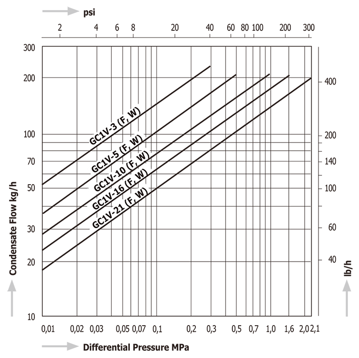
Discharge Capacity
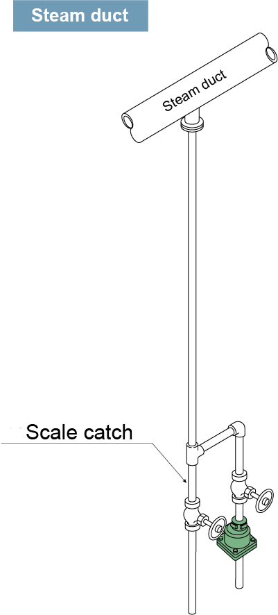
Installation Examples
GC1 Horizontal installation
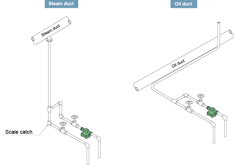
GC1V Vertical installation
Download
* Membership registration is required to download the documents.
Features
No condensate logging on primary side (continuous discharge float system with self-adjusting orifice)
The floating mechanism discharges condensate immediately at saturation temperature, preventing condensate stacking up on the primary side. Ideally installed in applications where condensate logging cannot be accepted.
Outstanding sealing performance
Achieves high sealing performance and reduces steam loss due to a precision polished float. The float is specially manufactured to comply with the maximum requirements for shape precision and surface tolerance. In combination with the specifically lapped valve, MIYAWAKI provides one of the tightest free floating valve designs in the market.
Auto blow-off system (built-in bimetal)
Automatically discharges initial air and cold condensate.
Compact design
The lever free design consists of less components, therefore reduces potentially defective parts and related maintenance and inspection efforts.
Stainless steel
With the exception of the bimetal, all components are made from corrosion-resistance stainless steel providing superb durability even in contact with aggressive additions in steam.
Typical applications
Suitable for steam main lines, steam tracing, and other such applications.
Dimensions/Weight
Screwed
| Size | Dimensions (mm) | Dimensions (in) | Weight | |||||
| L | W | W1 | L | W | W1 | (kg) | (lb) | |
| 1/2” | 127 | 86 | 53 | 5.0 | 3.4 | 2.09 | 1,8 | 4.0 |
| 3/4” | 136 | 5.4 | 1,9 | 4.2 | ||||
| 1” | 140 | 51 | 5.5 | 2.01 | 2,0 | 4.4 | ||
Flanged
| Size | Dimensions (mm) | Dimensions (in) | Weight (kg) | Weight (lb) | ||||||||||||
| L | W | W1 | L | W | W1 | ASME/JPI (RF) | DIN | JIS (FF) | JIS (RF) | ASME/JPI (RF) | DIN | JIS (FF) | JIS (RF) | |||
| 150lb | 300lb | PN40 | 10K,16K | 20K | 150lb | 300lb | PN40 | 10K,16K | 20K | |||||||
| 1/2" | 175 | 86 | 53 | 6.9 | 3.4 | 2.09 | 2,9 | 3,3 | 3,3 | 3,3 | 3,5 | 6.4 | 7.3 | 7.3 | 7.3 | 7.7 |
| 3/4" | 195 | 7.7 | 3,5 | 4,5 | 4,5 | 3,8 | 4,0 | 7.7 | 9.9 | 9.9 | 8.4 | 8.8 | ||||
| 1" | 215 | 8.5 | 4,2 | 5,3 | 5,3 | 5,0 | 5,3 | 9.2 | 11.7 | 11.7 | 11.0 | 11.7 | ||||
Socket Weld
| Size | Dimensions (mm) | Dimensions (in) | Weight | |||||||||||
| L | W | W1 | D | C | h | L | W | W1 | D | C | h | (kg) | (lb) | |
| 1/2” | 127 | 86 | 53 | 36 | 22,2 | 15 | 5.0 | 3.4 | 2.1 | 1.4 | 0.9 | 0.6 | 1,8 | 4.0 |
| 3/4” | 136 | 41 | 27,7 | 5.4 | 1.6 | 1.1 | 1,9 | 4.2 | ||||||
| 1” | 140 | 51 | 50 | 34,5 | 5.5 | 2.0 | 2.0 | 1.4 |
2,0 |
4.4 | ||||
| Model | Connection |
Max. operating pressure |
Max. operating differential pressure |
Max. operating temperature |
Body material |
||||
| Type | Size |
PMO (MPa) |
PMO (psig) |
⊿PMX (MPa) |
⊿PMX (psig) |
TMO (℃) |
TMO (℉) |
||
| GC1V-10 | Screwed Rc,NPT |
1/2” | 1,0 | 145 | 1,0 | 145 | 350 | 662 |
Stainless cast steel SCS13A/CF8 |
| 3/4” | |||||||||
| 1” | |||||||||
| GC1V-16 | 1/2” | 1,6 | 230 | 1,6 | 230 | ||||
| 3/4” | |||||||||
| 1” | |||||||||
| GC1V-21 | 1/2” | 2,1 | 305 | 2,1 | 305 | ||||
| 3/4” | |||||||||
| 1” | |||||||||
| GC1V-10F |
Flanged FF,RF |
1/2” | 1,0 | 145 | 1,0 | 145 | |||
| 3/4” | |||||||||
| 1” | |||||||||
| GC1V-16F | 1/2” | 1,6 | 230 | 1,6 | 230 | ||||
| 3/4” | |||||||||
| 1” | |||||||||
| GC1V-21F | 1/2” | 2,1 | 305 | 2,1 | 305 | ||||
| 3/4” | |||||||||
| 1” | |||||||||
| GC1V-10W |
Socket Weld SW |
1/2” | 1,0 | 145 | 1,0 | 145 | |||
| 3/4” | |||||||||
| 1” | |||||||||
| GC1V-16W | 1/2” | 1,6 | 230 | 1,6 | 230 | ||||
| 3/4” | |||||||||
| 1” | |||||||||
| GC1V-21W | 1/2” | 2,1 | 305 | 2,1 | 305 | ||||
| 3/4” | |||||||||
| 1” | |||||||||
●Maximum allowable pressure (PMA): 2,1MPa (305psig) PMA is the pressure that can be tolerated by pressure-resistant parts (body).
●Maximum allowable temperature (TMA): 350℃ (662℉) TMA is the temperature that can be tolerated by pressure-resistant parts (body).
●Minimum operating differential pressure (⊿PMN): 0,01MPa (1.5psig) ⊿PMN is the minimum operating differential pressure between the trap inlet and outlet.
*Available flange standards: ASME/JPI, DIN, JIS
GC1 Horizontal installation
GC1V Vertical installation
* Membership registration is required to download the documents.