Series S | Thermodynamic Disc Steam Traps
Steam Traps Series S | Thermodynamic Disc Steam Traps
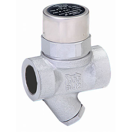
S55H
High pressure specification, Dedicated to steam main lines
Features/Applications
Features
Compact and cost effective design
It is space saving, simple mechanism with very few moving components.
Easy maintenance
The minimum amount of moving parts and easy in-line access ensure easy and fast maintenance.
Flexible installation
This product can be installed either horizontally or vertically.
Auto blow off and air vent
Thanks to a bimetal ring, the trap smoothly discharges initial air and cold condensate. (Auto blow-off mechanism)
Tailored design
Manufacturing with custom face-to-face dimensions is possible.
Typical applications
Dedicated to high temperature and high pressure steam main lines
Dimensions/Weight
Dimensions/Weight
Screwed / Socket Weld
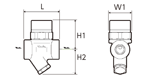
| Size | Dimensions (mm) | Dimensions (in) | Weight | |||||||
| L | H1 | H2 | W | L | H1 | H2 | W | (kg) | (lb) | |
| 1/2” | 70 | 60 | 52 | 45 | 2.8 | 2.4 | 2.1 | 1.8 | 1,0 | 2.2 |
| 3/4” | ||||||||||
| 1” | 75 | 65 | 56 | 3.0 | 2.6 | 2.2 | 1,2 | 2.6 | ||
Flanged
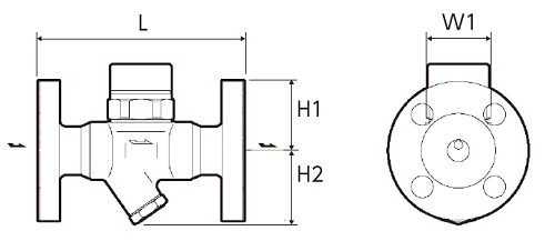
JIS,ASME
| Size | Dimensions (mm) | Dimensions (in) | Weight (kg) | Weight (lb) | ||||||||||||||||
| L | H1 | H2 | W | L | H1 | H2 | W | JIS(FF,RF) | ASME/JPI(RF) | JIS(FF,RF) | ASME/JPI(RF) | |||||||||
| 10K,16K | 20K | 30K,40K | 150lb | 300lb | 600lb | 10K,16K | 20K | 30K,40K | 150lb | 300lb | 600lb | |||||||||
| 1/2” | 140 | 60 | 52 | 45 | 5.5 | 2.4 | 2.1 | 1.8 | 2,6 | 2,8 | 4,0 | 2,6 | 3,1 | 3,2 | 5.7 | 6.2 | 8.8 | 5.7 | 6.8 | 7.1 |
| 3/4” | 165 | 6.5 | 3,1 | 3,3 | 4,4 | 3,1 | 4,0 | 4,2 | 6.8 | 7.3 | 9.7 | 6.8 | 8.8 | 9.3 | ||||||
| 1” | 175 | 6.9 | 4,2 | 4,5 | 5,6 | 4,2 | 5,5 | 5,7 | 9.3 | 9.9 | 12.4 | 9.3 | 12.1 | 12.6 | ||||||
DIN PN40 PN100
| Size | Dimensions (mm) | Dimensions (in) |
Weight DIN PN40 |
Weight PN100 |
||||||||
| L | H1 | H2 | W | L | H1 | H2 | W | (kg) | (lb) | (kg) | (lb) | |
| DN15 | 150 | 60 | 52 | 45 | 5.9 | 2.4 | 2.0 | 1.8 | 3,1 | 6.8 | 3,7 | 8.2 |
| DN20 | 3,7 | 8.2 | 5,3 | 11.7 | ||||||||
| DN25 | 160 | 6.3 | 4,4 | 9.7 | 6,3 | 13.9 | ||||||
*Customized face-to-face dimensions on request.
*Please contact MIYAWAKI for further information.
Specifications
| Model | Connection |
Max. operating pressure |
Max. operating pressure differential |
Max. operating temperature |
Body material |
||||
| Type | Size |
PMO (MPa) |
PMO (psig) |
(MPa) | (psig) |
TMO (℃) |
TMO (℉) |
||
| S55H |
Screwed Rc,NPT |
1/2” | 4,6 | 667 | 4,6 | 667 | 425 | 800 |
Forged steel A105 |
| 3/4” | |||||||||
| 1” | |||||||||
| S55HF |
Flanged FF,RF |
1/2” | |||||||
| 3/4” | |||||||||
| 1” | |||||||||
| S55HW |
Socket Weld SW |
1/2” | |||||||
| 3/4” | |||||||||
| 1” | |||||||||
●Maximum allowable pressure (PMA): 4,6MPa (667psig)
PMA is the pressure that can be tolerated by pressure-resistant parts (body).
●Maximum allowable temperature (TMA): 425℃ (800℉)
TMA is the temperature that can be tolerated by pressure-resistant parts (body).
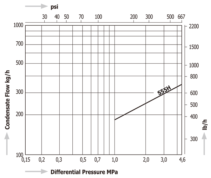
Discharge Capacity
Download
* Membership registration is required to download the documents.
Features
Compact and cost effective design
It is space saving, simple mechanism with very few moving components.
Easy maintenance
The minimum amount of moving parts and easy in-line access ensure easy and fast maintenance.
Flexible installation
This product can be installed either horizontally or vertically.
Auto blow off and air vent
Thanks to a bimetal ring, the trap smoothly discharges initial air and cold condensate. (Auto blow-off mechanism)
Tailored design
Manufacturing with custom face-to-face dimensions is possible.
Typical applications
Dedicated to high temperature and high pressure steam main lines
Dimensions/Weight
Screwed / Socket Weld
| Size | Dimensions (mm) | Dimensions (in) | Weight | |||||||
| L | H1 | H2 | W | L | H1 | H2 | W | (kg) | (lb) | |
| 1/2” | 70 | 60 | 52 | 45 | 2.8 | 2.4 | 2.1 | 1.8 | 1,0 | 2.2 |
| 3/4” | ||||||||||
| 1” | 75 | 65 | 56 | 3.0 | 2.6 | 2.2 | 1,2 | 2.6 | ||
Flanged
JIS,ASME
| Size | Dimensions (mm) | Dimensions (in) | Weight (kg) | Weight (lb) | ||||||||||||||||
| L | H1 | H2 | W | L | H1 | H2 | W | JIS(FF,RF) | ASME/JPI(RF) | JIS(FF,RF) | ASME/JPI(RF) | |||||||||
| 10K,16K | 20K | 30K,40K | 150lb | 300lb | 600lb | 10K,16K | 20K | 30K,40K | 150lb | 300lb | 600lb | |||||||||
| 1/2” | 140 | 60 | 52 | 45 | 5.5 | 2.4 | 2.1 | 1.8 | 2,6 | 2,8 | 4,0 | 2,6 | 3,1 | 3,2 | 5.7 | 6.2 | 8.8 | 5.7 | 6.8 | 7.1 |
| 3/4” | 165 | 6.5 | 3,1 | 3,3 | 4,4 | 3,1 | 4,0 | 4,2 | 6.8 | 7.3 | 9.7 | 6.8 | 8.8 | 9.3 | ||||||
| 1” | 175 | 6.9 | 4,2 | 4,5 | 5,6 | 4,2 | 5,5 | 5,7 | 9.3 | 9.9 | 12.4 | 9.3 | 12.1 | 12.6 | ||||||
DIN PN40 PN100
| Size | Dimensions (mm) | Dimensions (in) |
Weight DIN PN40 |
Weight PN100 |
||||||||
| L | H1 | H2 | W | L | H1 | H2 | W | (kg) | (lb) | (kg) | (lb) | |
| DN15 | 150 | 60 | 52 | 45 | 5.9 | 2.4 | 2.0 | 1.8 | 3,1 | 6.8 | 3,7 | 8.2 |
| DN20 | 3,7 | 8.2 | 5,3 | 11.7 | ||||||||
| DN25 | 160 | 6.3 | 4,4 | 9.7 | 6,3 | 13.9 | ||||||
*Customized face-to-face dimensions on request.
*Please contact MIYAWAKI for further information.
| Model | Connection |
Max. operating pressure |
Max. operating pressure differential |
Max. operating temperature |
Body material |
||||
| Type | Size |
PMO (MPa) |
PMO (psig) |
(MPa) | (psig) |
TMO (℃) |
TMO (℉) |
||
| S55H |
Screwed Rc,NPT |
1/2” | 4,6 | 667 | 4,6 | 667 | 425 | 800 |
Forged steel A105 |
| 3/4” | |||||||||
| 1” | |||||||||
| S55HF |
Flanged FF,RF |
1/2” | |||||||
| 3/4” | |||||||||
| 1” | |||||||||
| S55HW |
Socket Weld SW |
1/2” | |||||||
| 3/4” | |||||||||
| 1” | |||||||||
●Maximum allowable pressure (PMA): 4,6MPa (667psig)
PMA is the pressure that can be tolerated by pressure-resistant parts (body).
●Maximum allowable temperature (TMA): 425℃ (800℉)
TMA is the temperature that can be tolerated by pressure-resistant parts (body).
* Membership registration is required to download the documents.