Series S | Thermodynamic Disc Steam Traps
Steam Traps Series S | Thermodynamic Disc Steam Traps
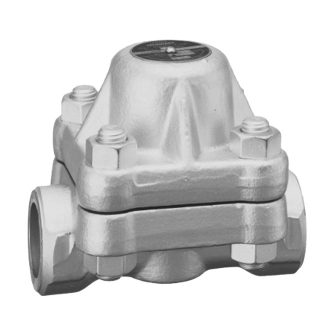
S62N
Features/Applications
Features
Versatile steam trap
It has a wide range of operating pressure, making it suitable for various applications.
Flexible installation
This product can be installed either horizontally or vertically.
Superb durability
It is equipped with an additional cover to improve thermal efficiency and reduce cycling frequency, enhancing durability.
Auto blow off and air vent
Thanks to a bimetal ring, the trap smoothly discharges initial air and cold condensate. (Auto blow-off mechanism)
Tailored design
Manufacturing with custom face-to-face dimensions is possible.
Typical applications
Suitable for a wide range of applications such as steam main lines and steam tracing.
Dimensions/Weight
Dimensions/Weight
Screwed / Socket Weld
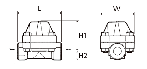
| Size | Dimensions (mm) | Dimensions (in) | Weight | |||||||
| L | H1 | H2 | W | L | H1 | H2 | W | (kg) | (lb) | |
| 1/2” | 130 | 90 | 25 | 100 | 5.1 | 3.5 | 1.0 | 3.9 | 5,7 | 12.6 |
| 3/4” | ||||||||||
| 1” | ||||||||||
Flanged
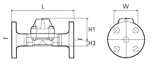
JIS,ASME
| Model | Size | Dimensions (mm) | Dimensions (in) | Weight (kg) | Weight (lb) | ||||||||||||||||||||
| L | H1 | H2 | W | L | H1 | H2 | W | JIS(RF) | ASME/JPI(RF) | JIS(RF) | ASME/JPI(RF) | ||||||||||||||
| 20K | 30K | 40K | 63K | 150lb | 300lb | 600lb | 900lb | 20K | 30K | 40K | 63K | 150lb | 300lb | 600lb | 900lb | ||||||||||
| S62NF | 1/2” | 200 (220)※ |
90 | 25 | 100 | 7.9 (8.7)※ |
3.5 | 1.0 | 3.9 | 7,3 | 8,4 | 8,7 | 9,6 | 6,7 | 7,2 | 7,3 | 9,6 | 16.1 | 18.5 | 19.2 | 21.2 | 14.8 | 15.9 | 16.1 | 21.2 |
| 3/4” | 210 (230)※ |
8.3 (9.1)※ |
7,7 | 8,9 | 9,2 | 11,1 | 7,7 | 8,2 | 8,5 | 10,9 | 17.0 | 19.6 | 20.3 | 24.5 | 17.0 | 18.1 | 18.7 | 24.0 | |||||||
| 1” | 240 | 9.4 | 9,2 | 10,1 | 10,5 | 12,1 | 8,3 | 9,4 | 9,6 | 13,3 | 20.3 | 22.3 | 23.2 | 26.7 | 18.3 | 20.7 | 21.2 | 29.3 | |||||||
DIN PN63 PN100
| Size | Dimensions (mm) | Dimensions (in) |
Weight |
|||||||
| L | H1 | H2 | W | L | H1 | H2 | W | (kg) | (lb) | |
| DN15 | 210 | 90 | 25 | 100 | 8.3 | 3.5 | 1.0 | 3.9 | 9,4 | 20.7 |
| DN20 | 230 | 9.1 | 11,4 | 25.1 | ||||||
| DN25 | 12,5 | 27.6 | ||||||||
*Customized face-to-face dimensions on request.
*Please contact MIYAWAKI for further information.
Specifications
| Model | Connection |
Max. operating pressure |
Max. operating pressure differential |
Max. operating temperature |
Body material |
||||
| Type | Size |
PMO (MPa) |
PMO (psig) |
(MPa) | (psig) |
TMO (℃) |
TMO (℉) |
||
| S62N |
Screwed Rc,NPT |
1/2” | 6,5 | 942.5 | 6,5 | 942.5 | 475 | 887 |
Chromium molybdenum steel A182 F22 |
| 3/4” | |||||||||
| 1” | |||||||||
| S62NF |
Flanged FF,RF |
1/2” | |||||||
| 3/4” | |||||||||
| 1” | |||||||||
| S62NW |
Socket Weld SW |
1/2” | |||||||
| 3/4” | |||||||||
| 1” | |||||||||
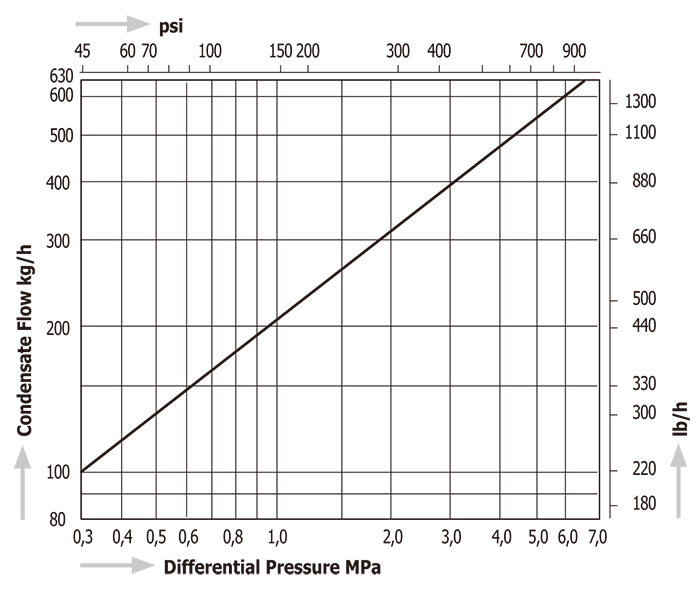
Discharge Capacity
Download
* Membership registration is required to download the documents.
Features
Versatile steam trap
It has a wide range of operating pressure, making it suitable for various applications.
Flexible installation
This product can be installed either horizontally or vertically.
Superb durability
It is equipped with an additional cover to improve thermal efficiency and reduce cycling frequency, enhancing durability.
Auto blow off and air vent
Thanks to a bimetal ring, the trap smoothly discharges initial air and cold condensate. (Auto blow-off mechanism)
Tailored design
Manufacturing with custom face-to-face dimensions is possible.
Typical applications
Suitable for a wide range of applications such as steam main lines and steam tracing.
Dimensions/Weight
Screwed / Socket Weld
| Size | Dimensions (mm) | Dimensions (in) | Weight | |||||||
| L | H1 | H2 | W | L | H1 | H2 | W | (kg) | (lb) | |
| 1/2” | 130 | 90 | 25 | 100 | 5.1 | 3.5 | 1.0 | 3.9 | 5,7 | 12.6 |
| 3/4” | ||||||||||
| 1” | ||||||||||
Flanged
JIS,ASME
| Model | Size | Dimensions (mm) | Dimensions (in) | Weight (kg) | Weight (lb) | ||||||||||||||||||||
| L | H1 | H2 | W | L | H1 | H2 | W | JIS(RF) | ASME/JPI(RF) | JIS(RF) | ASME/JPI(RF) | ||||||||||||||
| 20K | 30K | 40K | 63K | 150lb | 300lb | 600lb | 900lb | 20K | 30K | 40K | 63K | 150lb | 300lb | 600lb | 900lb | ||||||||||
| S62NF | 1/2” | 200 (220)※ |
90 | 25 | 100 | 7.9 (8.7)※ |
3.5 | 1.0 | 3.9 | 7,3 | 8,4 | 8,7 | 9,6 | 6,7 | 7,2 | 7,3 | 9,6 | 16.1 | 18.5 | 19.2 | 21.2 | 14.8 | 15.9 | 16.1 | 21.2 |
| 3/4” | 210 (230)※ |
8.3 (9.1)※ |
7,7 | 8,9 | 9,2 | 11,1 | 7,7 | 8,2 | 8,5 | 10,9 | 17.0 | 19.6 | 20.3 | 24.5 | 17.0 | 18.1 | 18.7 | 24.0 | |||||||
| 1” | 240 | 9.4 | 9,2 | 10,1 | 10,5 | 12,1 | 8,3 | 9,4 | 9,6 | 13,3 | 20.3 | 22.3 | 23.2 | 26.7 | 18.3 | 20.7 | 21.2 | 29.3 | |||||||
DIN PN63 PN100
| Size | Dimensions (mm) | Dimensions (in) |
Weight |
|||||||
| L | H1 | H2 | W | L | H1 | H2 | W | (kg) | (lb) | |
| DN15 | 210 | 90 | 25 | 100 | 8.3 | 3.5 | 1.0 | 3.9 | 9,4 | 20.7 |
| DN20 | 230 | 9.1 | 11,4 | 25.1 | ||||||
| DN25 | 12,5 | 27.6 | ||||||||
*Customized face-to-face dimensions on request.
*Please contact MIYAWAKI for further information.
| Model | Connection |
Max. operating pressure |
Max. operating pressure differential |
Max. operating temperature |
Body material |
||||
| Type | Size |
PMO (MPa) |
PMO (psig) |
(MPa) | (psig) |
TMO (℃) |
TMO (℉) |
||
| S62N |
Screwed Rc,NPT |
1/2” | 6,5 | 942.5 | 6,5 | 942.5 | 475 | 887 |
Chromium molybdenum steel A182 F22 |
| 3/4” | |||||||||
| 1” | |||||||||
| S62NF |
Flanged FF,RF |
1/2” | |||||||
| 3/4” | |||||||||
| 1” | |||||||||
| S62NW |
Socket Weld SW |
1/2” | |||||||
| 3/4” | |||||||||
| 1” | |||||||||
* Membership registration is required to download the documents.