Series S | Thermodynamic Disc Steam Traps
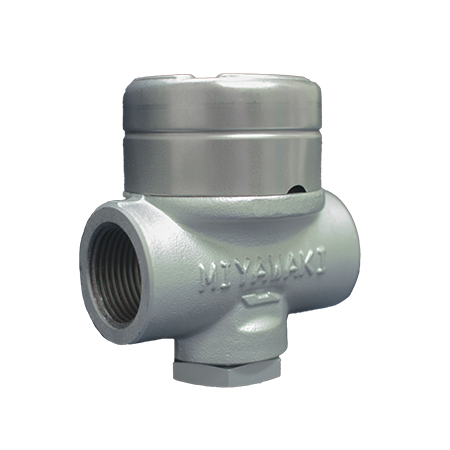
Steam Traps Series S | Thermodynamic Disc Steam Traps
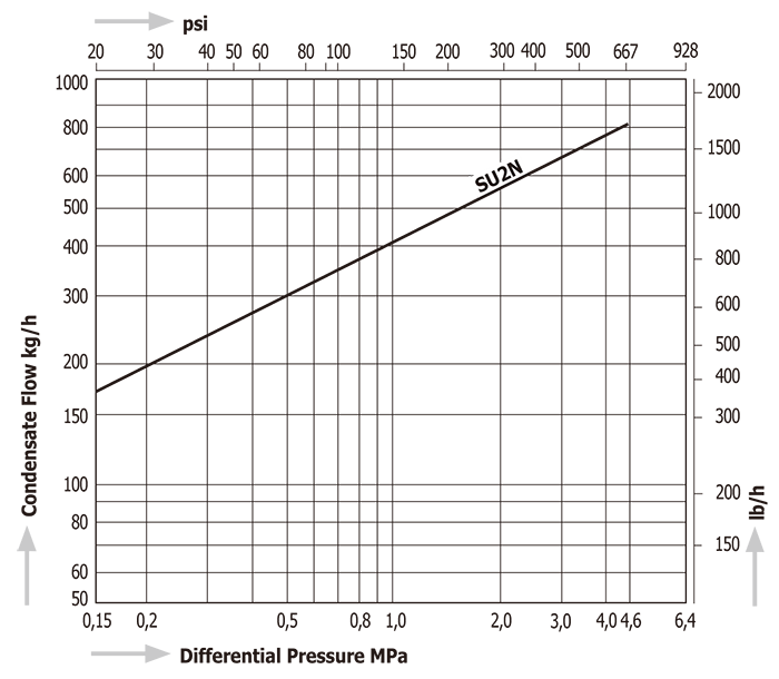
SU2N
Features/Applications
Features
Flexible installation
This product can be installed either horizontally or vertically.
Superb durability
The body of the product is made from stainless steel, making it durable and corrosion-resistant, even in aggressive media.
Auto blow off and air vent
Thanks to a bimetal ring, the trap smoothly discharges initial air and cold condensate. (Auto blow-off mechanism)
Tailored design
Manufacturing with custom face-to-face dimensions is possible.
Typical applications
Suitable for high temperature and pressure steam main lines, steam tracing, and other such applications.
Dimensions/Weight
Dimensions/Weight
Screwed
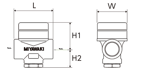
| Size | Dimensions (mm) | Dimensions (in) | Weight | |||||||
| L | H1 | H2 | W | L | H1 | H2 | W | (kg) | (lb) | |
| 1/2” | 70 | 47 | 32 | 53 | 2.8 | 1.9 | 1.3 | 2.1 | 0,8 | 1.8 |
| 3/4” | ||||||||||
| 1” | 75 | 51 | 3.0 | 2.0 | 1,0 | 2.2 | ||||
Socket Weld
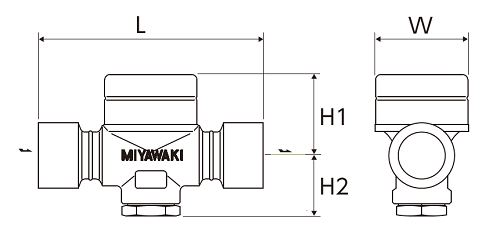
| Size | Dimensions (mm) | Dimensions (in) | Weight | |||||||
| L | H1 | H2 | W | L | H1 | H2 | W | (kg) | (lb) | |
| 1/2” | 140 | 47 | 32 | 53 | 5.51 | 1.85 | 1.26 | 2.09 | 1,5 | 3.3 |
| 3/4” | 1,4 | 3.1 | ||||||||
| 1” | 1,3 | 2.9 | ||||||||
Flanged
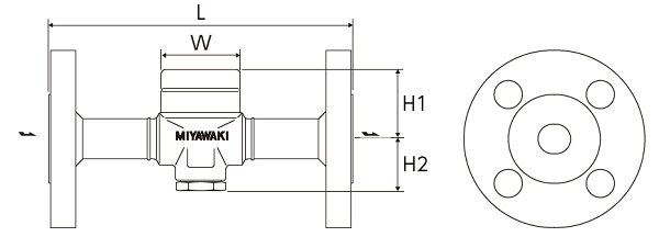
JIS,ASME
| Size | Dimensions (mm) | Dimensions (in) | Weight (kg) | Weight (lb) | ||||||||||||||||
| L | H1 | H2 | W | L | H1 | H2 | W | JIS(FF,RF) | ASME/JPI(RF) | JIS(FF,RF) | ASME/JPI(RF) | |||||||||
| 10K,16K,20K | 30K | 40K | 150lb | 300lb | 600lb | 10K,16K,20K | 30K | 40K | 150lb | 300lb | 600lb | |||||||||
| 1/2” | 205 | 47 | 32 | 53 | 8.1 | 1.9 | 1.3 | 2.1 | 2,6 | 3,8 | 4,1 | 2,2 | 2,7 | 3,3 | 5.7 | 8.4 | 9.0 | 4.9 | 6.0 | 7.3 |
| 3/4” | 3,0 | 4,1 | 4,4 | 2,6 | 3,7 | 4,6 | 6.6 | 9.0 | 9.7 | 5.7 | 8.2 | 10.1 | ||||||||
| 1” | 4,0 | 5,0 | 5,4 | 3,0 | 4,3 | 5,4 | 8.8 | 11.0 | 11.9 | 6.6 | 9.5 | 11.9 | ||||||||
DIN PN40
| Size | Dimensions (mm) | Dimensions (in) | Weight | |||||||
| L | H1 | H2 | W | L | H1 | H2 | W | (kg) | (lb) | |
| DN15 | 150 | 47 | 32 | 53 | 5.9 | 1.9 | 1.3 | 2.1 | 2,6 | 5.7 |
| DN20 | 3,3 | 7.3 | ||||||||
| DN25 | 160 | 6.3 | 3,8 | 8.4 | ||||||
*Customized face-to-face dimensions on request.
*Please contact MIYAWAKI for further information.
Specifications
| Model | Connection |
Max. operating pressure |
Max. operating pressure differential |
Max. operating temperature |
Body material |
||||
| Type | Size |
PMO (MPa) |
PMO (psig) |
(MPa) | (psig) |
TMO (℃) |
TMO (℉) |
||
|
SU2N |
Screwed Rc,NPT |
1/2” | 4,6 | 667 | 4,6 | 667 | 425 | 800 |
Stainless steel SUS 420J2 |
| 3/4” | |||||||||
| 1” | |||||||||
| SU2NF |
Flanged FF,RF |
1/2” | |||||||
| 3/4” | |||||||||
| 1” | |||||||||
| SU2NW |
Socket Weld SW |
1/2” | |||||||
| 3/4” | |||||||||
| 1” | |||||||||
●SU2NF flange and pipe are carbon steel
●SU2NW welded parts are carbon steel
●Maximum allowable pressure (PMA): 6,4MPa (928psig) (SU2N)
PMA is the pressure that can be tolerated by pressure-resistant parts (body).
●Maximum allowable temperature (TMA): 425℃ (800℉)
TMA is the temperature that can be tolerated by pressure-resistant parts (body).
Discharge Capacity
Download
* Membership registration is required to download the documents.
Features
Flexible installation
This product can be installed either horizontally or vertically.
Superb durability
The body of the product is made from stainless steel, making it durable and corrosion-resistant, even in aggressive media.
Auto blow off and air vent
Thanks to a bimetal ring, the trap smoothly discharges initial air and cold condensate. (Auto blow-off mechanism)
Tailored design
Manufacturing with custom face-to-face dimensions is possible.
Typical applications
Suitable for high temperature and pressure steam main lines, steam tracing, and other such applications.
Dimensions/Weight
Screwed
| Size | Dimensions (mm) | Dimensions (in) | Weight | |||||||
| L | H1 | H2 | W | L | H1 | H2 | W | (kg) | (lb) | |
| 1/2” | 70 | 47 | 32 | 53 | 2.8 | 1.9 | 1.3 | 2.1 | 0,8 | 1.8 |
| 3/4” | ||||||||||
| 1” | 75 | 51 | 3.0 | 2.0 | 1,0 | 2.2 | ||||
Socket Weld
| Size | Dimensions (mm) | Dimensions (in) | Weight | |||||||
| L | H1 | H2 | W | L | H1 | H2 | W | (kg) | (lb) | |
| 1/2” | 140 | 47 | 32 | 53 | 5.51 | 1.85 | 1.26 | 2.09 | 1,5 | 3.3 |
| 3/4” | 1,4 | 3.1 | ||||||||
| 1” | 1,3 | 2.9 | ||||||||
Flanged
JIS,ASME
| Size | Dimensions (mm) | Dimensions (in) | Weight (kg) | Weight (lb) | ||||||||||||||||
| L | H1 | H2 | W | L | H1 | H2 | W | JIS(FF,RF) | ASME/JPI(RF) | JIS(FF,RF) | ASME/JPI(RF) | |||||||||
| 10K,16K,20K | 30K | 40K | 150lb | 300lb | 600lb | 10K,16K,20K | 30K | 40K | 150lb | 300lb | 600lb | |||||||||
| 1/2” | 205 | 47 | 32 | 53 | 8.1 | 1.9 | 1.3 | 2.1 | 2,6 | 3,8 | 4,1 | 2,2 | 2,7 | 3,3 | 5.7 | 8.4 | 9.0 | 4.9 | 6.0 | 7.3 |
| 3/4” | 3,0 | 4,1 | 4,4 | 2,6 | 3,7 | 4,6 | 6.6 | 9.0 | 9.7 | 5.7 | 8.2 | 10.1 | ||||||||
| 1” | 4,0 | 5,0 | 5,4 | 3,0 | 4,3 | 5,4 | 8.8 | 11.0 | 11.9 | 6.6 | 9.5 | 11.9 | ||||||||
DIN PN40
| Size | Dimensions (mm) | Dimensions (in) | Weight | |||||||
| L | H1 | H2 | W | L | H1 | H2 | W | (kg) | (lb) | |
| DN15 | 150 | 47 | 32 | 53 | 5.9 | 1.9 | 1.3 | 2.1 | 2,6 | 5.7 |
| DN20 | 3,3 | 7.3 | ||||||||
| DN25 | 160 | 6.3 | 3,8 | 8.4 | ||||||
*Customized face-to-face dimensions on request.
*Please contact MIYAWAKI for further information.
| Model | Connection |
Max. operating pressure |
Max. operating pressure differential |
Max. operating temperature |
Body material |
||||
| Type | Size |
PMO (MPa) |
PMO (psig) |
(MPa) | (psig) |
TMO (℃) |
TMO (℉) |
||
|
SU2N |
Screwed Rc,NPT |
1/2” | 4,6 | 667 | 4,6 | 667 | 425 | 800 |
Stainless steel SUS 420J2 |
| 3/4” | |||||||||
| 1” | |||||||||
| SU2NF |
Flanged FF,RF |
1/2” | |||||||
| 3/4” | |||||||||
| 1” | |||||||||
| SU2NW |
Socket Weld SW |
1/2” | |||||||
| 3/4” | |||||||||
| 1” | |||||||||
●SU2NF flange and pipe are carbon steel
●SU2NW welded parts are carbon steel
●Maximum allowable pressure (PMA): 6,4MPa (928psig) (SU2N)
PMA is the pressure that can be tolerated by pressure-resistant parts (body).
●Maximum allowable temperature (TMA): 425℃ (800℉)
TMA is the temperature that can be tolerated by pressure-resistant parts (body).
* Membership registration is required to download the documents.