Series TB | Temperature Control Steam Traps
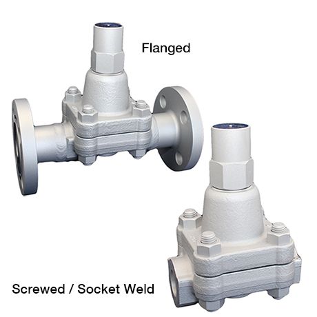
Steam Traps Series TB | Temperature Control Steam Traps
TB52
1975 Received CP Idea Award at the Chemical Plant Show / 1977 Received the Award for Energy Saving Excellence / 1980 Received the Japan Machinery Federation’s Energy-Efficient Machinery Award
Features/Applications
Features
Complete steam containment
The temperature control trap operates with an adjustable subcooling of condensate. Thus maintaining a certain condensate level in the trap. This mechanism provides a 100% tight sealing and effectively prevents steam loss during operation.
Suitable for high pressure, high temperature ranges and superheated steam
Superb durability
The MIYAWAKI SCCV (Self Closing and Centering Valve) System has the effect of increasing durability by achieving soft closing during operation.
Consisting of a free rotating valve that is centered and guided by the condensate flow, hence perfectly fitted in the valve seat even under extreme conditions of high pressure applications. This significantly reduces wear and erosion of the valve components.Quick startup
Swiftly discharges the initial cold condensate and air.
Also fulfils the function of an air vent.
Energy saving effect
A significant energy saving effect is achieved by controlling the temperature of discharged condensate.
With low operating noise and very little flash steam
Typical applications
Suitable for steam main lines, trace lines, and other such applications.
Dimensions/Weight
Dimensions/Weight
Screwed / Socket Weld
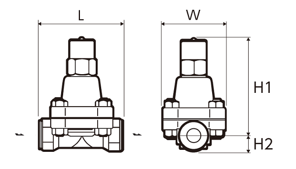
| Size | Dimensions (mm) | Dimensions (in) | Weight | |||||||
| L | H1 | H2 | W | L | H1 | H2 | W | (kg) | (lb) | |
| 1/2” | 130 | 155 | 25 | 100 | 5.1 | 6.1 | 1.0 | 3.9 |
5,7 |
12.6 |
| 3/4” | ||||||||||
| 1” | ||||||||||
Flanged
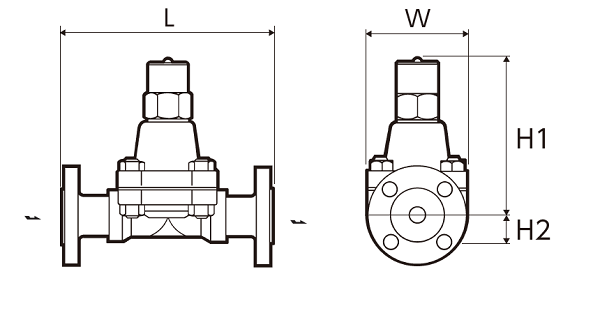
| Size | Flange standards | Dimensions (mm) | Dimensions (in) | Weight | ||||||||
| L | H1 | H2 | W | L | H1 | H2 | W | (kg) | (lb) | |||
| 1/2” | JIS (RF) |
20K |
200 |
155 | 25 | 100 | 7.9 | 6.1 | 0.98 | 3.94 |
7,3 |
16.1 |
| 30K | 8,4 | 18.5 | ||||||||||
| 40K | 8,7 | 19.2 | ||||||||||
| 63K | 220 | 8.7 | 9,6 | 21.2 | ||||||||
| ASME/JPI (RF) |
150lb | 200 | 7.9 | 6,7 | 14.8 | |||||||
| 300lb | 7,2 | 15.9 | ||||||||||
| 600lb | 7,3 | 16.1 | ||||||||||
| 900lb | 220 | 8.7 | 9,6 | 21.2 | ||||||||
| 3/4” | JIS (RF) |
20K | 210 | 8.3 | 7,7 | 17.0 | ||||||
| 30K | 8,9 | 19.6 | ||||||||||
| 40K | 9,2 | 20.3 | ||||||||||
| 63K | 230 | 9.1 | 11,1 | 24.5 | ||||||||
| ASME/JPI (RF) |
150lb | 210 | 8.3 | 7,7 | 17.0 | |||||||
| 300lb | 8,2 | 18.1 | ||||||||||
| 600lb | 8,5 | 18.7 | ||||||||||
| 900lb | 230 | 9.1 | 10,9 | 24.0 | ||||||||
| 1” | JIS (RF) |
20K | 240 | 9.5 | 9,2 | 20.3 | ||||||
| 30K | 10,1 | 22.3 | ||||||||||
| 40K | 10,5 | 23.2 | ||||||||||
| 63K | 12,1 | 26.7 | ||||||||||
| ASME/JPI (RF) |
150lb | 8,3 | 18.3 | |||||||||
| 300lb | 9,4 | 20.7 | ||||||||||
| 600lb | 9,6 | 21.2 | ||||||||||
| 900lb | 13,3 | 29.3 | ||||||||||
| Size | Flange standards | Dimensions (mm) | Dimensions (in) | Weight | ||||||||
| L | H1 | H2 | W | L | H1 | H2 | W | (kg) | (lb) | |||
| DN15 | DIN PN63/PN100 | 210 | 155 | 25 | 100 | 8.3 | 6.1 | 1.0 | 3.9 | 9,4 | 20.7 | |
| DN20 | 230 | 9.1 | 11,4 | 25.1 | ||||||||
| DN25 | 12,1 | 26.7 | ||||||||||
*Customized face-to-face dimensions on request.
*Please contact MIYAWAKI for further information.
Specifications
| Model | Connection |
Max. operating pressure |
Max. operating differential pressure |
Max. operating temperature |
Adjustable range |
Standard set temperature |
Body material |
||||||
| Type | Size | (MPa) | (psig) | (MPa) | (psig) |
TMO (℃) |
TMO (℉) |
(℃) | (℉) | (℃) | (℉) | ||
| TB52-45 |
Screwed Rc,NPT |
1/2” |
4,5 |
653 | 4,5 | 653 | 475 | 887 | 100 - 220 | 212 - 428 |
180 (at 2,1MPa) |
356 (at 305psig) |
Chromium molybdenum steel |
| 3/4” | |||||||||||||
| 1” | |||||||||||||
| TB52-65 | 1/2” | 6,5 | 943 | 6,5 | 943 | 100 - 240 | 212 - 464 |
220 (at 4,4MPa) |
428 (at 638psig) |
||||
| 3/4” | |||||||||||||
| 1” | |||||||||||||
| TB52F-45 |
Flanged RF
|
1/2” | 4,5 | 653 | 4,5 | 653 | 100 - 220 | 212 - 428 |
180 (at 2,1MPa) |
356 (at 305psig) |
|||
| 3/4” | |||||||||||||
| 1” | |||||||||||||
| TB52F-65 | 1/2” | 6,5 | 943 | 6,5 | 943 | 100 - 240 | 212 - 464 |
220 (at 4,4MPa) |
428 (at 638psig) |
||||
| 3/4” | |||||||||||||
| 1” | |||||||||||||
| TB52W-45 |
Socket Weld SW
|
1/2” | 4,5 | 653 | 4,5 | 653 | 100 - 220 | 212 - 428 |
180 (at 2,1MPa) |
356 (at 305psig) |
|||
| 3/4” | |||||||||||||
| 1” | |||||||||||||
| TB52W-65 | 1/2” | 6,5 | 943 | 6,5 | 943 | 100 - 240 | 212 - 464 |
220 (at 4,4MPa) |
428 (at 638psig) |
||||
| 3/4” | |||||||||||||
| 1” | |||||||||||||
*It is possible to change the standard factory set temperature. Specify the operating pressure and set temperature.
*Please refer to the installation manual how to adjust the set temperature.
Discharge Capacity
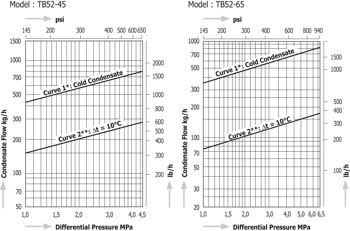
●⊿t is the difference between the temperature of a temperature control trap when the valve is initially opened and condensate temperature. The temperature difference (⊿t) upon the initial passage of air is great, and indicates that the flow rate will also increase.
* Curve1 shows the trap's maximum capacity when discharaging cold condensate.
**Curve2 shows the trap's maximum capacity when discharaging hot condensate at a temperature of 10°C (18°F) below the adjusted temperature of the trap.
Download
* Membership registration is required to download the documents.
Features
Complete steam containment
The temperature control trap operates with an adjustable subcooling of condensate. Thus maintaining a certain condensate level in the trap. This mechanism provides a 100% tight sealing and effectively prevents steam loss during operation.
Suitable for high pressure, high temperature ranges and superheated steam
Superb durability
The MIYAWAKI SCCV (Self Closing and Centering Valve) System has the effect of increasing durability by achieving soft closing during operation.
Consisting of a free rotating valve that is centered and guided by the condensate flow, hence perfectly fitted in the valve seat even under extreme conditions of high pressure applications. This significantly reduces wear and erosion of the valve components.Quick startup
Swiftly discharges the initial cold condensate and air.
Also fulfils the function of an air vent.
Energy saving effect
A significant energy saving effect is achieved by controlling the temperature of discharged condensate.
With low operating noise and very little flash steam
Typical applications
Suitable for steam main lines, trace lines, and other such applications.
Dimensions/Weight
Screwed / Socket Weld
| Size | Dimensions (mm) | Dimensions (in) | Weight | |||||||
| L | H1 | H2 | W | L | H1 | H2 | W | (kg) | (lb) | |
| 1/2” | 130 | 155 | 25 | 100 | 5.1 | 6.1 | 1.0 | 3.9 |
5,7 |
12.6 |
| 3/4” | ||||||||||
| 1” | ||||||||||
Flanged
| Size | Flange standards | Dimensions (mm) | Dimensions (in) | Weight | ||||||||
| L | H1 | H2 | W | L | H1 | H2 | W | (kg) | (lb) | |||
| 1/2” | JIS (RF) |
20K |
200 |
155 | 25 | 100 | 7.9 | 6.1 | 0.98 | 3.94 |
7,3 |
16.1 |
| 30K | 8,4 | 18.5 | ||||||||||
| 40K | 8,7 | 19.2 | ||||||||||
| 63K | 220 | 8.7 | 9,6 | 21.2 | ||||||||
| ASME/JPI (RF) |
150lb | 200 | 7.9 | 6,7 | 14.8 | |||||||
| 300lb | 7,2 | 15.9 | ||||||||||
| 600lb | 7,3 | 16.1 | ||||||||||
| 900lb | 220 | 8.7 | 9,6 | 21.2 | ||||||||
| 3/4” | JIS (RF) |
20K | 210 | 8.3 | 7,7 | 17.0 | ||||||
| 30K | 8,9 | 19.6 | ||||||||||
| 40K | 9,2 | 20.3 | ||||||||||
| 63K | 230 | 9.1 | 11,1 | 24.5 | ||||||||
| ASME/JPI (RF) |
150lb | 210 | 8.3 | 7,7 | 17.0 | |||||||
| 300lb | 8,2 | 18.1 | ||||||||||
| 600lb | 8,5 | 18.7 | ||||||||||
| 900lb | 230 | 9.1 | 10,9 | 24.0 | ||||||||
| 1” | JIS (RF) |
20K | 240 | 9.5 | 9,2 | 20.3 | ||||||
| 30K | 10,1 | 22.3 | ||||||||||
| 40K | 10,5 | 23.2 | ||||||||||
| 63K | 12,1 | 26.7 | ||||||||||
| ASME/JPI (RF) |
150lb | 8,3 | 18.3 | |||||||||
| 300lb | 9,4 | 20.7 | ||||||||||
| 600lb | 9,6 | 21.2 | ||||||||||
| 900lb | 13,3 | 29.3 | ||||||||||
| Size | Flange standards | Dimensions (mm) | Dimensions (in) | Weight | ||||||||
| L | H1 | H2 | W | L | H1 | H2 | W | (kg) | (lb) | |||
| DN15 | DIN PN63/PN100 | 210 | 155 | 25 | 100 | 8.3 | 6.1 | 1.0 | 3.9 | 9,4 | 20.7 | |
| DN20 | 230 | 9.1 | 11,4 | 25.1 | ||||||||
| DN25 | 12,1 | 26.7 | ||||||||||
*Customized face-to-face dimensions on request.
*Please contact MIYAWAKI for further information.
| Model | Connection |
Max. operating pressure |
Max. operating differential pressure |
Max. operating temperature |
Adjustable range |
Standard set temperature |
Body material |
||||||
| Type | Size | (MPa) | (psig) | (MPa) | (psig) |
TMO (℃) |
TMO (℉) |
(℃) | (℉) | (℃) | (℉) | ||
| TB52-45 |
Screwed Rc,NPT |
1/2” |
4,5 |
653 | 4,5 | 653 | 475 | 887 | 100 - 220 | 212 - 428 |
180 (at 2,1MPa) |
356 (at 305psig) |
Chromium molybdenum steel |
| 3/4” | |||||||||||||
| 1” | |||||||||||||
| TB52-65 | 1/2” | 6,5 | 943 | 6,5 | 943 | 100 - 240 | 212 - 464 |
220 (at 4,4MPa) |
428 (at 638psig) |
||||
| 3/4” | |||||||||||||
| 1” | |||||||||||||
| TB52F-45 |
Flanged RF
|
1/2” | 4,5 | 653 | 4,5 | 653 | 100 - 220 | 212 - 428 |
180 (at 2,1MPa) |
356 (at 305psig) |
|||
| 3/4” | |||||||||||||
| 1” | |||||||||||||
| TB52F-65 | 1/2” | 6,5 | 943 | 6,5 | 943 | 100 - 240 | 212 - 464 |
220 (at 4,4MPa) |
428 (at 638psig) |
||||
| 3/4” | |||||||||||||
| 1” | |||||||||||||
| TB52W-45 |
Socket Weld SW
|
1/2” | 4,5 | 653 | 4,5 | 653 | 100 - 220 | 212 - 428 |
180 (at 2,1MPa) |
356 (at 305psig) |
|||
| 3/4” | |||||||||||||
| 1” | |||||||||||||
| TB52W-65 | 1/2” | 6,5 | 943 | 6,5 | 943 | 100 - 240 | 212 - 464 |
220 (at 4,4MPa) |
428 (at 638psig) |
||||
| 3/4” | |||||||||||||
| 1” | |||||||||||||
*It is possible to change the standard factory set temperature. Specify the operating pressure and set temperature.
*Please refer to the installation manual how to adjust the set temperature.
●⊿t is the difference between the temperature of a temperature control trap when the valve is initially opened and condensate temperature. The temperature difference (⊿t) upon the initial passage of air is great, and indicates that the flow rate will also increase.
* Curve1 shows the trap's maximum capacity when discharaging cold condensate.
**Curve2 shows the trap's maximum capacity when discharaging hot condensate at a temperature of 10°C (18°F) below the adjusted temperature of the trap.
* Membership registration is required to download the documents.