Series TB | Temperature Control Steam Traps
Steam Traps Series TB | Temperature Control Steam Traps
TB7N-SR
Features/Applications
Features
Takes only 1/10th of the previous time required to remove scale
Disassembly before cleaning is no longer needed. Remove scale instantly by simply turning a handle with no need to stop the flow of steam. The time required is approximately 3 minutes per trap.
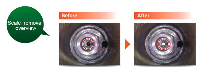
Elimination of flow channel-blocking scale
Lots of scale builds up in the flow channel (valve hole inlet and outlet) of temperature control traps. Scale removal work is performed from below the valve hole, so it is possible to get rid of all scale.
Pre-emptive action before closing performance deteriorates
This product enables efficient regular scale removal work. Poor closing performance caused by scale can be prevented through regular scale removal.
Superb durability
The MIYAWAKI SCCV (Self Closing and Centering Valve) System has the effect of increasing durability by achieving soft closing during operation.
Consisting of a free rotating valve that is centered and guided by the condensate flow, hence perfectly fitted in the valve seat even under extreme conditions of high pressure applications. This significantly reduces wear and erosion of the valve components.
Typical applications
Suitable for steam main lines, trace lines, and other such applications.
Dimensions/Weight
Dimensions/Weight
Screwed / Socket Weld
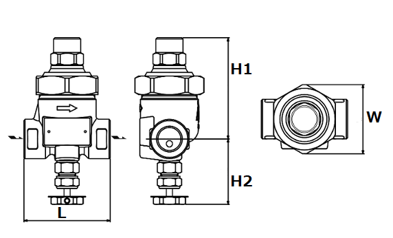
| Size | Dimensions (mm) | Dimensions (in) | Weight | |||||||
| L | H1 | H2 | W | L | H1 | H2 | W | (kg) | (lb) | |
| 1/2” | 70 | 82 | 54 | 56 | 2.8 | 3.2 | 2.1 | 2.2 | 1,0 | 2.2 |
| 3/4” | 80 | 3.2 | 1,1 | 2.4 | ||||||
| 1” | 1,2 | 2.7 | ||||||||
Flanged
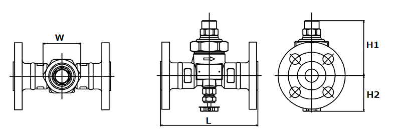
JIS,ASME
| Size | Dimensions (mm) | Dimensions (in) | Weight (kg) | Weight (lb) | ||||||||||||||
| L | H1 | H2 | W | L | H1 | H2 | W | JIS(FF,RF) | JIS(RF) | ASME/JPI(RF) | JIS(FF,RF) | JIS(RF) | ASME/JPI(RF) | |||||
| 10K,16K | 20K | 30K | 150lb | 300lb | 10K,16K | 20K | 30K | 150lb | 300lb | |||||||||
| 1/2” | 145 | 82 | 54 | 56 | 5.7 | 3.2 | 2.1 | 2.2 |
2,5 |
2,6 | 2,7 | 2,1 | 2,6 | 5.5 | 5.7 | 6.0 | 4.6 | 5.7 |
| 3/4” | 2,9 | 3,0 | 3,1 | 2,6 | 3,5 | 6.4 | 6.6 | 6.8 | 5.7 | 7.7 | ||||||||
| 1” | 4,0 | 4,2 | 4,3 | 3,3 | 4,3 | 8.8 | 9.3 | 9.5 | 7.3 | 9.5 | ||||||||
DIN PN40
|
Size |
Dimensions (mm) | Dimensions (in) |
Weight |
|||||||
| L | H1 | H2 | W | L | H1 | H2 | W | (kg) | (lb) | |
| DN15 | 150 | 82 | 54 | 56 | 5.9 | 3.2 | 2.1 | 2.2 | 2,7 | 6.0 |
| DN20 | 3,5 | 7.7 | ||||||||
| DN25 | 160 | 6.3 | 4,1 | 9.0 | ||||||
*Customized face-to-face dimensions on request.
*Please contact MIYAWAKI for further information.
Specifications
| Model | Connection |
Max. operating pressure |
Max. operating differential pressure |
Max. operating temperature |
Adjustable range |
Standard set temperature |
Body material |
||||||
| Type | Size |
PMO (MPa) |
PMO (psig) |
(MPa) | (psig) |
TMO (℃) |
TMO (℉) |
(℃) | (℉) | (℃) | (℉) | ||
| TB7N-SR |
Screwed Rc,NPT |
1/2” |
2,1 |
305 | 2,1 | 305 | 230 | 446 | 50 - 200 | 122 - 392 |
100 (at 1,0MPa) |
212 (at 145psig) |
Forged steel A105 |
| 3/4” | |||||||||||||
| 1” | |||||||||||||
| TB7NF-SR |
Flanged FF,RF |
1/2” | |||||||||||
| 3/4” | |||||||||||||
| 1” | |||||||||||||
| TB7NW-SR |
Socket Weld SW |
1/2” | |||||||||||
| 3/4” | |||||||||||||
| 1” | |||||||||||||
*Installation in both horizontal and vertical piping is possible, but please install with a downward tilt to ensure condensate can easily run into the steam trap.
*It is possible to change the standard factory set temperature. Please specify the operating pressure and set temperature.
*Please refer to the installation manual how to adjust the set temperature.
Discharge Capacity
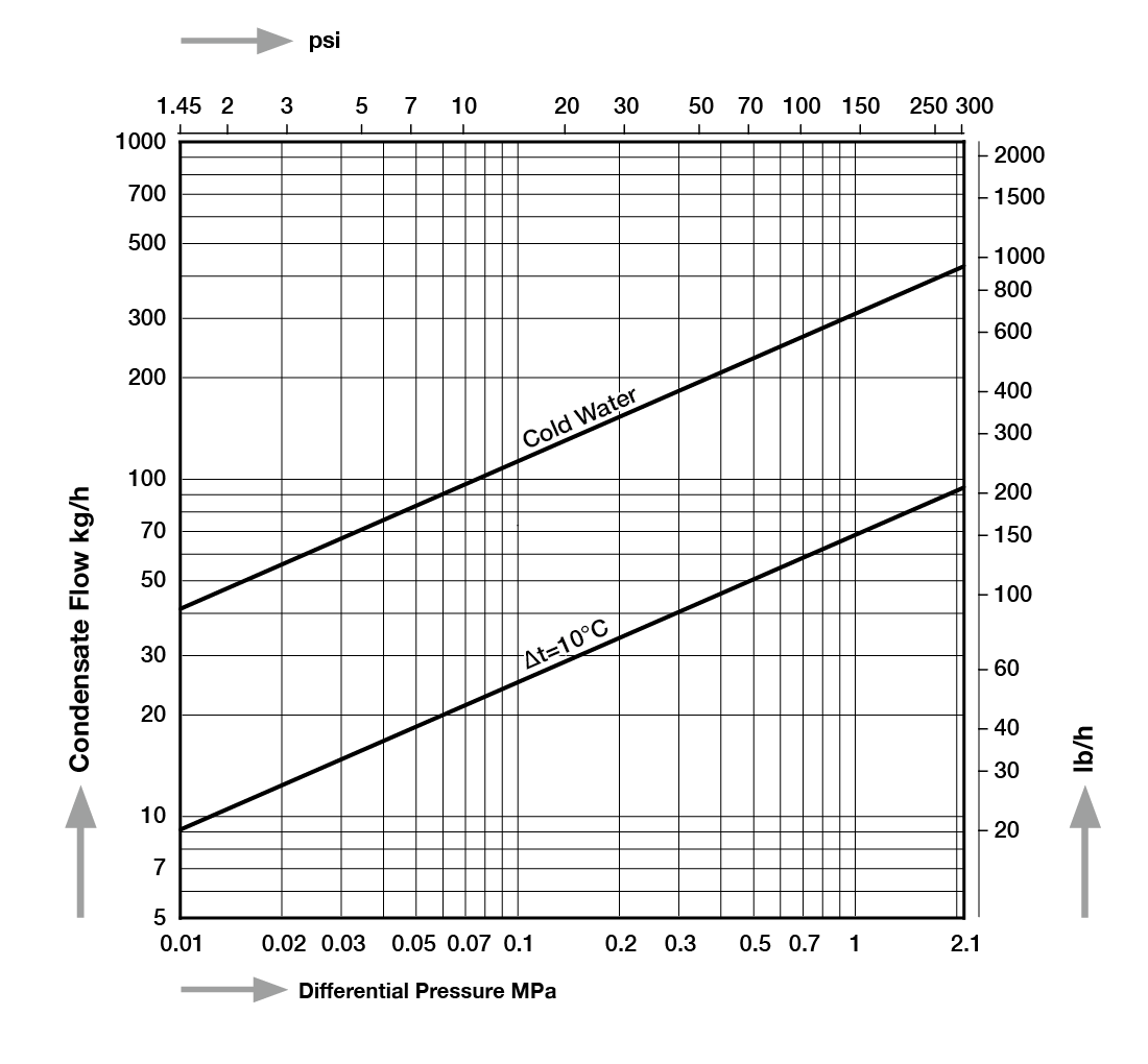
●Δt value is the difference of temperature between the real temperature of the discharging condensate and the adjusted temperature of the trap. The temperature difference (⊿t) upon the initial passage of air is great, and indicates that the flow rate will also increase.
● The condensate flow rate listed in this table is the value when the product is set to 100℃ and discharging condensate at 90℃.
* The "Cold Water" shows the trap's maximum capacity when discharging cold condensate.
* The Δt=10℃ shows the trap's maximum capacity when discharging hot condensate at a temperature of 10°C (18°F) below the adjusted temperature of the trap.
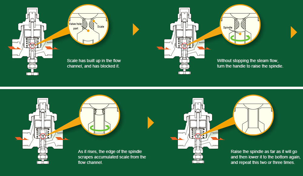
Procedure for scale removal
[TB9N-SR example]
Download
* Membership registration is required to download the documents.
Features
Takes only 1/10th of the previous time required to remove scale
Disassembly before cleaning is no longer needed. Remove scale instantly by simply turning a handle with no need to stop the flow of steam. The time required is approximately 3 minutes per trap.
Elimination of flow channel-blocking scale
Lots of scale builds up in the flow channel (valve hole inlet and outlet) of temperature control traps. Scale removal work is performed from below the valve hole, so it is possible to get rid of all scale.
Pre-emptive action before closing performance deteriorates
This product enables efficient regular scale removal work. Poor closing performance caused by scale can be prevented through regular scale removal.
Superb durability
The MIYAWAKI SCCV (Self Closing and Centering Valve) System has the effect of increasing durability by achieving soft closing during operation.
Consisting of a free rotating valve that is centered and guided by the condensate flow, hence perfectly fitted in the valve seat even under extreme conditions of high pressure applications. This significantly reduces wear and erosion of the valve components.
Typical applications
Suitable for steam main lines, trace lines, and other such applications.
Dimensions/Weight
Screwed / Socket Weld
| Size | Dimensions (mm) | Dimensions (in) | Weight | |||||||
| L | H1 | H2 | W | L | H1 | H2 | W | (kg) | (lb) | |
| 1/2” | 70 | 82 | 54 | 56 | 2.8 | 3.2 | 2.1 | 2.2 | 1,0 | 2.2 |
| 3/4” | 80 | 3.2 | 1,1 | 2.4 | ||||||
| 1” | 1,2 | 2.7 | ||||||||
Flanged
JIS,ASME
| Size | Dimensions (mm) | Dimensions (in) | Weight (kg) | Weight (lb) | ||||||||||||||
| L | H1 | H2 | W | L | H1 | H2 | W | JIS(FF,RF) | JIS(RF) | ASME/JPI(RF) | JIS(FF,RF) | JIS(RF) | ASME/JPI(RF) | |||||
| 10K,16K | 20K | 30K | 150lb | 300lb | 10K,16K | 20K | 30K | 150lb | 300lb | |||||||||
| 1/2” | 145 | 82 | 54 | 56 | 5.7 | 3.2 | 2.1 | 2.2 |
2,5 |
2,6 | 2,7 | 2,1 | 2,6 | 5.5 | 5.7 | 6.0 | 4.6 | 5.7 |
| 3/4” | 2,9 | 3,0 | 3,1 | 2,6 | 3,5 | 6.4 | 6.6 | 6.8 | 5.7 | 7.7 | ||||||||
| 1” | 4,0 | 4,2 | 4,3 | 3,3 | 4,3 | 8.8 | 9.3 | 9.5 | 7.3 | 9.5 | ||||||||
DIN PN40
|
Size |
Dimensions (mm) | Dimensions (in) |
Weight |
|||||||
| L | H1 | H2 | W | L | H1 | H2 | W | (kg) | (lb) | |
| DN15 | 150 | 82 | 54 | 56 | 5.9 | 3.2 | 2.1 | 2.2 | 2,7 | 6.0 |
| DN20 | 3,5 | 7.7 | ||||||||
| DN25 | 160 | 6.3 | 4,1 | 9.0 | ||||||
*Customized face-to-face dimensions on request.
*Please contact MIYAWAKI for further information.
| Model | Connection |
Max. operating pressure |
Max. operating differential pressure |
Max. operating temperature |
Adjustable range |
Standard set temperature |
Body material |
||||||
| Type | Size |
PMO (MPa) |
PMO (psig) |
(MPa) | (psig) |
TMO (℃) |
TMO (℉) |
(℃) | (℉) | (℃) | (℉) | ||
| TB7N-SR |
Screwed Rc,NPT |
1/2” |
2,1 |
305 | 2,1 | 305 | 230 | 446 | 50 - 200 | 122 - 392 |
100 (at 1,0MPa) |
212 (at 145psig) |
Forged steel A105 |
| 3/4” | |||||||||||||
| 1” | |||||||||||||
| TB7NF-SR |
Flanged FF,RF |
1/2” | |||||||||||
| 3/4” | |||||||||||||
| 1” | |||||||||||||
| TB7NW-SR |
Socket Weld SW |
1/2” | |||||||||||
| 3/4” | |||||||||||||
| 1” | |||||||||||||
*Installation in both horizontal and vertical piping is possible, but please install with a downward tilt to ensure condensate can easily run into the steam trap.
*It is possible to change the standard factory set temperature. Please specify the operating pressure and set temperature.
*Please refer to the installation manual how to adjust the set temperature.
●Δt value is the difference of temperature between the real temperature of the discharging condensate and the adjusted temperature of the trap. The temperature difference (⊿t) upon the initial passage of air is great, and indicates that the flow rate will also increase.
● The condensate flow rate listed in this table is the value when the product is set to 100℃ and discharging condensate at 90℃.
* The "Cold Water" shows the trap's maximum capacity when discharging cold condensate.
* The Δt=10℃ shows the trap's maximum capacity when discharging hot condensate at a temperature of 10°C (18°F) below the adjusted temperature of the trap.
[TB9N-SR example]
* Membership registration is required to download the documents.