-
Effective Use of Steam and Steam Traps
-
Pumping Traps
-
-
-
Condensate recovery is mostly carried out only by discharging capacity based on the differential pressure between inlet and outlet sides of the steam trap. If the condensate recovery line is long or has rising lines, it is difficult to recover condensate through discharge capacity alone. In such a recovery system, it is necessary to install a condensate recovery pump to pump the condensate to the required location, as described in the previous example.
There are two types of condensate recovery pump: electric pumps and mechanical pumps, also called pumping traps. Electric pumps are superior to mechanical pumps in being able to handle large quantities of condensate, but mechanical pumps can also exhibit their full potential under the following conditions.
-
The temperature of condensate is high, and cavitation may occur when an electric pump is used
-
The condensate pressure drops below atmospheric pressure.
-
Hazardous environments where explosive substances are handled, which are also known as explosion-proof designated areas.
-
It is difficult to provide electric power.
-
-
There are two types of pumping traps. One operates on the assumption that the outlet pressure is higher than the inlet pressure of pumping trap, and the other type has a built-in steam trap mechanism, and operates regardless of the pressure relationship between inlet and outlet sides.
-
-
-
-
Operating principle of pumping traps
The general operating principles of the pumping trap are described below using a type without a built-in steam trap.
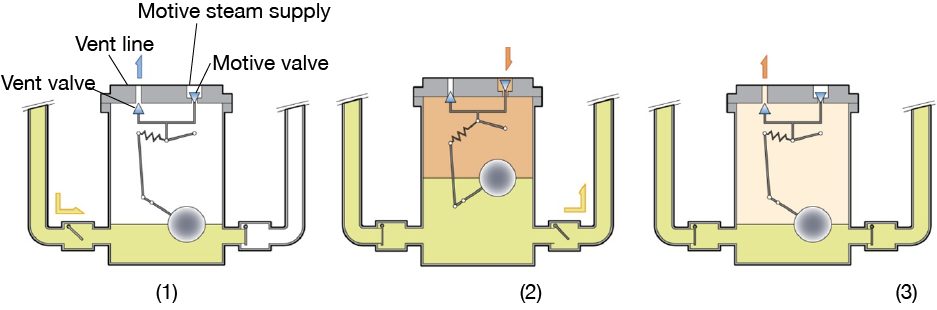
Figure 5.8 Operating principles of pumping traps
-
(1) The float (spherical) in the body of pumping trap is lowered, which opens the vent valve and closes the motive valve. Condensate, which is led higher than the pumping trap, flows into the body through the check valve on the inlet side
-
(2) As the amount of condensate increases, the float rises to a certain level, and the snap-action mechanism is activated, causing the vent valve to close and opening the motive valve, allowing high-pressure motive fluid to flow through the motive valve and increase the pressure in the main unit. Soon, the pressure in the main unit becomes higher than the pressure at the outlet side, and condensate is pushed out through outlet side check valve.
-
(3) When the condensate is pushed out, the water level in the main unit drops and the float descends to a predetermined position, the switching mechanism works again to close the motive valve and open the vent valve. The motive valve closes and the vent valve opens. As the motive fluid is exhausted from the vent valve, the pressure in the main unit decreases, which is called the "equalization process”.
When the check valve on the inlet side opens again, condensate flows into the main unit, and the process from inflow to equalization is repeated.
-
-
-
Basic installation line example
-
-
-
Figure 5.9 shows the basic installation configuration of the pumping traps. Condensate generated in equipment that uses steam such as heat exchangers flows into the receiver tank once through steam trap. Since the receiver tank is located above the pumping trap, the condensate flows into the pumping trap body by its head pressure. During the pumping process, the motive media flows into the pumping trap. Possible motive media are not only steam, but also air and nitrogen gas. The exhausted motive media is returned to the receiver tank through an equalization line. This reduces the pressure in the body of the pumping trap to almost the same pressure as the receiver tank.
The inlet and outlet check valves, the equalization line, and receiver tank are necessary elements. This example is an open system in which the receiver tank is open to the atmosphere, but there are also closed systems that recover condensate at pressures higher than atmospheric pressure.
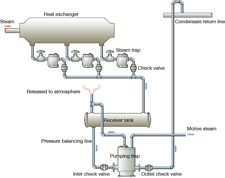
Figure 5.9 Installation line example of a pumping trap