-
Precautions for Installing Steam Traps
-
Piping on the Primary Side of Steam Traps
-
This section discusses precautions about condensate discharging lines which are installed in the main steam lines, and condensate discharging lines are installed in the equipment.
-
Steam main lines
In the steam mains, a part of the steam loses latent heat by heat radiation and is condensed, and to remove this condensate, several condensate discharge lines (branch lines) are often installed at intervals of 30m to 50m.
However, unlike the examples of the device described below, it is difficult to remove all the condensate since high-speed flowing condensate which is being pulled by high-speed steam and is moving, must be captured in the middle of it. Most of condensate generally occurred in the steam main line is in very small amounts, so a small diameter condensate discharge line is used. For this reason, where the condensate discharge line is connected to the steam main, it is recommended to set up a condensate collection pocket, as shown in Figure 4.1 nstalled as a means to increase the capture efficiency.
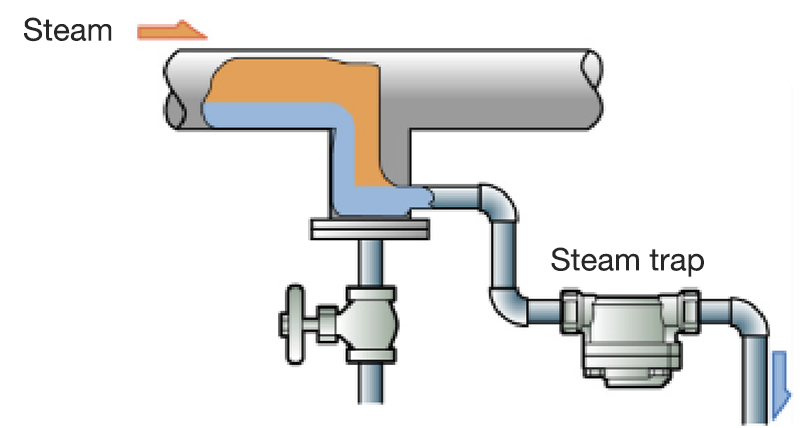
Figure 4.1 Condensate collection pocket
If the diameter of the main steam line is up to 100 mm, the diameter of the collecting pocket should be the same as that of the main steam line. On the other hand, if the diameter of the main steam line is 100 mm or more, the diameter of the collecting pocket should be at least half of that of the main steam line. Furthermore, since the bottom of the collecting pocket collects dust, the condensate outlet should be located slightly above the bottom of the pocket.
-
Individual trapping
Individual trapping refers to the trapping system where one steam trap is installed in each condensate discharge path, as shown in Figure 4.2.
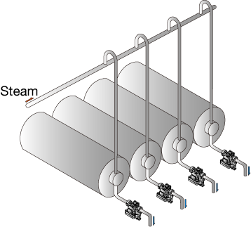
Figure 4.2 Individual trapping
In contrast, trapping in which the discharge paths of multiple units are connected to a single steam trap is installed in the common condensate discharged line and is called group trapping. (Figure 4.3)
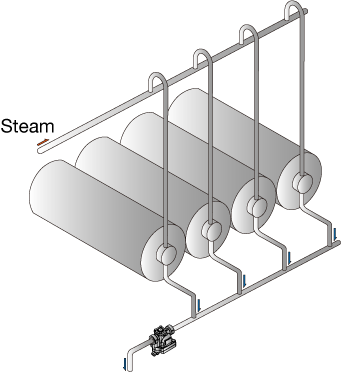
Figure 4.3 Group Trapping
Group trapping is often introduced in steam trapping courses as a typical example of improper trapping. The problems caused by group trapping are shown in Figure 4.4 and 4.5.
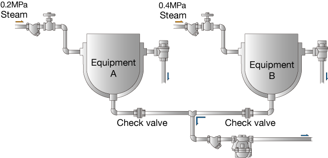
Figure 4.4 Equipment under different pressures
Figure 4.4 shows an incorrect configuration where a single steam trap is used to cover the condensate discharge of two devices used at different pressures. Since the pressure of equipment B is higher than that of equipment A, the generated condensate flows into the steam trap without difficulty. On the other hand, the high pressure from equipment B prevents the check valve on the A side from opening, preventing the condensate from being discharged from equipment A.
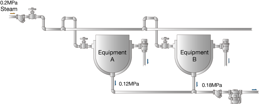
Figure 4.5 Equipment under the same pressure
Figure 4.5 shows the case where equipment is used at the same pressure with each other. It is assumed that equipment B is under normal operation, and the inside of equipment reaches the predefined temperature. If equipment A is started in this condition, it will produce much more condensate than equipment B because it is cooler inside. As more steam condenses, the pressure drops, which causes steam to flow in from equipment B. Equipment A will have to resist this steam and discharge condensate.
Thus, group trapping can prevent condensate from discharging smoothly, and negatively affect equipment performance. This configuration requires fewer steam traps, but this is caused by a lack of awareness of steam trapping. It is important to have a new understanding of the validity of individual trapping.
-
Installation position of the steam trap
It is generally recommended that when installing steam traps, in the condensate discharge, this is done as closely as possible to the equipment. The farther away the steam trap is from the equipment, the more likely it is that steam locking will occur between the steam trap and the equipment. The steam trap should also be installed in the lowest position of the condensate generator of the unit, for example, at or below the lowest point of the heat transfer line in the heat transfer device. (see Figure 4.6)
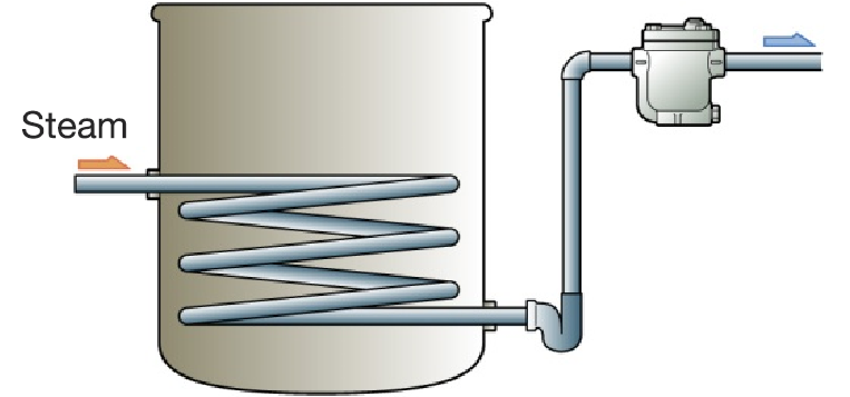
In case it is necessary to install the steam trap in the higher position, as shown in Figure 4.7, pay attention to the following points.
-
● A lift fitting is installed to set up the water seal.
● Use a smaller line than the stand-up line.
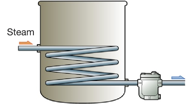
Figure 4.6 Correct mounting position of the steam trap
-
Figure 4.7 When installing lift fitting
The reason to use the water seal is as follows.
When the steam trap has finished discharging condensate, steam flows in and closes the valve, but at this time the start-up line is filled with steam. Eventually, condensate is generated again, but if a water seal is formed, when the steam in the start-up tube condenses and the pressure in the tube drops, the condensate immediately enters the tube and is quickly discharged through the steam trap.
On the other hand, if there is no water seal, when the steam in the start-up line condenses and the pressure drops, new steam enters the start-up line before the condensate. The amount of condensate increases, and the condensate discharge waits until the steam in the tube condenses. In this way, temporary steam locking is always caused when steam trap opens in the line, but if there is a water seal, it will be unlocked in a short period of time. If the diameter of the rising line can be further reduced, the unlocking time will be further shortened.
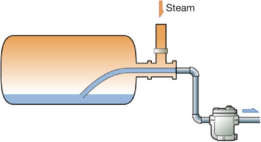
Figure 4.8 Cylinder dryer
The following is an example of equipment in which the steam traps are installed at a higher position than the condensate generator. In both cases, one end of the siphon tube is immersed in the condensate generator and the condensate is led to the steam trap through the trunnions.
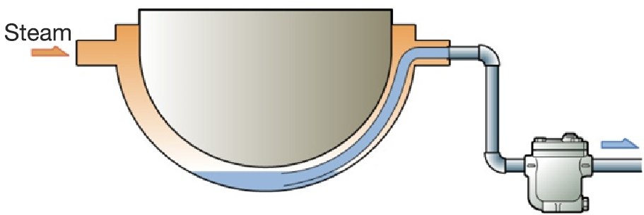
Figure 4.9 Rotating Double Boiler