-
Effective Use of Steam and Steam Traps
-
Effective Use of Condensate Heat
-
-
-
After the latent heat energy in the steam is released, steam is condensed, and changes to condensate. Condensate which is generated in various process equipment and heat transfer devices must be promptly discharged. If the condensate remains stagnant in this equipment, it may cause a decrease in heat-transfer efficiency and water-hammer when restarting operations. However, the discharged high temperature condensate has a lot of energy (sensible heat), and so is worth reusing.
The use of condensate heat falls into the following three categories.
-
Use of flash steam
-
Use of sensible heat with thermostatic steam traps
-
Condensate recovery
-
-
-
-
-
-
Use of flash steam
As described in “Flash steam”, some condensate will re-evaporate when it enters a low-pressure environment from a high-pressure environment, and becomes flash steam. The flash steam and steam produced from the boiler remains steam and this can be used as latent heat. The condensate from a high temperature heat transfer device is led to a flash tank set to an appropriate pressure, create flash steam, which is often used in low temperature heat transfer devices. In addition, condensate discharged from steam traps partially re-evaporates, and is used in the same way as described previously.
Figure 5.1 shows an example of a boiler factory. Condensate from a steam air pre-heater re-evaporates in a flash tank, and the created flash steam is provided to deaerator, with the rest of condensate being supplied to a low temperature feed water heater.
Please refer to Table 5.1 and 5.2 for the rate and the volume of flash steam generated in flash tanks.
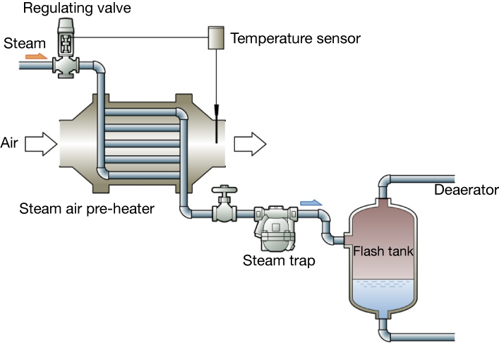
Figure 5.1 Use of flash steam in a boiler factory
Table 5.1 The amount of flash steam (%)
High-pressure side-pressure
(MPa)Flash tank pressure (MPa)
0
0.03
0.05
0.1
0.15
0.2
0.3
0.4
0.5
0.6
0.8
1.0
1.2
1.4
1.6
1.8
0.1
3.7
2.5
1.7
一
一
一
一
一
一
一
一
一
一
一
一
一
0.2
6.2
5.0
4.2
2.6
1.2
一
一
一
一
一
一
一
一
一
一
一
0.3
8.1
6.9
6.1
4.5
3.2
2.0
一
一
一
一
一
一
一
一
一
一
0.4
9.7
8.5
7.7
6.1
4.8
3.6
1.6
一
一
一
一
一
一
一
一
一
0.5
11.0
9.8
9.1
7.5
6.2
5.0
3.1
1.4
一
一
一
一
一
一
一
一
0.6
12.2
11.0
10.3
8.7
7.4
6.2
4.3
3.0
1.3
一
一
一
一
一
一
一
0.8
14.2
13.1
12.3
10.8
9.5
8.3
6.4
4.8
3.4
2.2
一
一
一
一
一
一
1.0
15.9
14.8
14.2
12.5
11.2
10.8
8.2
6.6
5.3
4.0
1.9
一
一
一
一
一
1.2
17.4
16.3
15.5
14.0
12.7
11.6
9.8
8.2
6.9
5.7
3.5
1.7
一
一
一
一
1.4
18.7
17.6
16.9
15.4
14.1
13.0
11.2
9.6
8.3
7.1
5.0
3.2
1.5
一
一
一
1.6
19.0
18.8
18.1
16.6
15.3
14.3
12.4
10.9
9.6
8.4
6.3
4.5
2.9
1.4
一
一
1.8
21.0
19.9
19.2
17.7
16.5
15.4
13.6
12.1
10.8
9.6
7.5
5.7
4.1
2.7
1.3
一
2.0
22.0
20.9
20.9
18.8
17.5
16.5
14.7
13.2
11.9
10.7
8.7
6.9
8.3
3.8
2.5
1.2
Table 5.2 The volume of re-evaporated steam (m3)
High-pressure side-pressure
(MPa)Pressures in flash tank (MPa)
0
0.03
0.05
0.1
0.15
0.2
0.3
0.4
0.5
0.6
0.8
1.0
1.2
1.4
1.6
1.8
0.1
61
33
20
一
一
一
一
一
一
一
一
一
一
一
一
一
0.2
103
67
50
23
9
一
一
一
一
一
一
一
一
一
一
一
0.3
135
93
72
41
23
12
一
一
一
一
一
一
一
一
一
一
0.4
161
115
91
55
35
22
8
一
一
一
一
一
一
一
一
一
0.5
184
133
107
68
45
31
14
5
一
一
一
一
一
一
一
一
0.6
203
149
122
78
54
38
20
11
4
一
一
一
一
一
一
一
0.8
237
176
145
97
70
51
30
13
11
6
一
一
一
一
一
一
1.0
266
199
168
113
82
62
39
25
17
11
4
一
一
一
一
一
1.2
290
219
183
126
93
72
46
31
22
16
8
3
一
一
一
一
1.4
312
237
199
139
103
80
53
37
27
20
11
6
2
一
一
一
1.6
332
254
214
150
112
88
59
42
31
23
14
8
4
2
一
一
1.8
351
269
227
160
121
95
64
46
35
27
16
10
6
4
2
一
2.0
368
279
238
170
128
102
69
50
38
30
19
12
8
5
3
1
-
-
-
Use of sensible heat through the use of thermostatic steam traps
A steam trap is a device that rapidly discharges generated condensate to outside of the system. Generally, the faster the condensate is discharged, the better its performance. We have found disadvantages, but no advantages to allowing condensate to remain in the system.
In the early 1970s, MIYAWAKI INC. developed a thermostatic steam trap that actively utilizes the sensible heat of the condensate by letting it stay in the trap, even though that is contrary to common sense. This was a revolutionary steam trap at that time because steam traps have a mechanism for setting appropriate condensate discharging temperature (clearly lower than the saturation temperature) in advance, and not discharging the condensate while it is above that temperature. In the midst of the first oil crisis and the rapidly growing awareness of the need for "energy saving," this temperature control trap was adopted one after another for steam tracing lines in factories, or replaced disk traps, etc., and this established its existence as an "energy-saving trap" in no time.
The main features of thermostatic steam traps are as follows.
-
Use condensate heat (sensible heat) effectively, especially for steam trace lines.
-
There is no steam leakage because a condensate seal is formed on the primary side of the steam trap body.
-
There is no (or little) flash steam because the temperature of condensate discharging is low.
It has the following benefits for steam trap performance
・ Reduces the erosion in valves and it has good durability
・ The condensate flow passage area on the secondary side of the steam trap outlets becomes substantially larger, and the size of condensate line piping can be reduced accordingly
Figure 5.2 shows the rate of steam saved by using latent heat.
For instance, when the condensate discharging temperature is set to 70℃ in 0.5 MPa (saturated steam temperature is 159 ℃), the rate of steam saved is approximately 15 % compared to the case when discharging condensate at saturated steam temperature.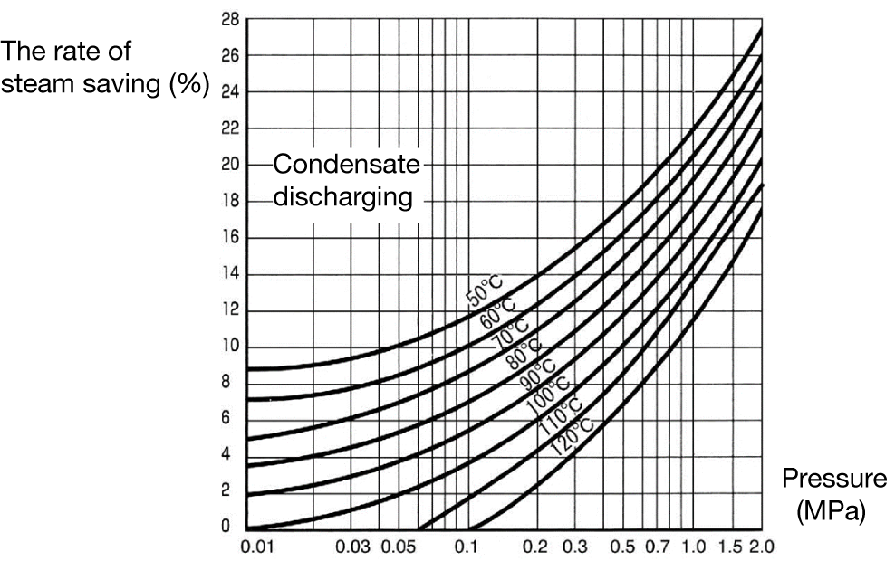
Figure 5.2 Condensate discharging temperature and the rate of steam saved
-
-
-
Condensate recovery
Condensate generated in steam system equipment is taken to the condensate discharging line. It is desirable both economically and environmentally that the condensate does not flow away, but is reused. There are several ways to reuse the condensate, and here we will discuss the recovery of the condensate into the boiler feedwater tank. The feature of this recovery and utilization is that the condensate itself is also reused.
A boiler is a type of equipment for heating and evaporating water at high pressure and discharging the created condensate to steam transport lines. Water must always maintain sufficient quality to be used in the boiler, and this is treated with chemical materials used for processing. Then, the water quality is checked and recovery treatment is performed if a decrease in the quality of water is detected. This treatment is called blowdown.
Thus steam creation in a boiler requires costs for fuel, as well as for water treatment agents and so on. The greater the number of blowdowns, the more boiler water and the other energy it contains will be disposed of. Condensate is virtually pure water after it has been treated and distilled. Thus, it is ideal for use as boiler water. Condensate should be actively recovered and this can bring the following benefits
-
Reduction in water supply costs
-
Reduction in fuel costs
-
Increasing the efficiency of steam creation from boilers
-
Reduction in boiler blow downs, and energy loss
-
Reduction of water treatment costs
The actual amount of effect varies from factory to factory and must be estimated independently, but the following example is helpful for estimating the approximate effect.
Set the prerequisites as follows:
(Precondition)1 USD = 140 YEN
The amount of boiler steam created :10,000kg/h Operating time :24 hours /day(8,760 hours /year) Temperature of boiler water supply :15℃ Condensate temperature :90℃(all of them are discharged, but not recovered) Boiler supply water costs :50 yen [0.35 USD]/m3 Boiler operation efficiency :85% Fuel cost (gas price) :2,000 yen [14.2 USD]/GJ(gigajour)(1.1 yen [0,007 USD]/kWh)
(1GJ=1,000,000kJ)(Fuel cost)
First, 1 kg of new raw water is needed for every 1 kg of unrecovered condensate. Calculate the cost of heating this raw water to 90°C. (⊿T=90℃-15℃=75℃) The amount of heat for increasing raw water temperature can be calculated according to the following formula.
Q=m×Cp×⊿T
Here,
Q :Amount of heat(kJ) m :Mass of material(kg) Cp :Specific heat of material(kJ/kg℃) (Specific heat of water is 4.19kJ/kg℃) ⊿T :Increased temperature of material(℃) In this example, m, Cp, ⊿T are 1kg, 4.19kJ/kg℃, 75℃, respectively. These values can be substituted in the formula as follows.
Q=1kg×4.19kJ/kg℃×75℃=314kJ
This is the amount of heat per unit mass.
Since this is the amount of heat per unit mass, we can calculate the annual heat requirement as 314 kJ/kg.
10,000kg/h×314kJ/kg×8,760h/year=27.506GJ
As the boiler efficiency is 85%, the actual amount of required heat can be calculated as below
27,506GJ/0.85=32,360GJ/year
Using the fuel cost (gas price) of 2,000 yen per GJ, the annual fuel cost is
32,360GJ/year ×2,000 yen [14.2 USD]/GJ=64,720,000 yen [462,285.7 USD]/year
(raw water price)
Next is the supplied water (raw water) cost. The price of water is determined by volume, and the density of ambient water is around 1,000kg/m3. Thus, the required annual amount of supplied water for which condensate is not recovered is as shown below.
(8,760h/year ×10,000kg/h)/(1,000kg/m3)=87,600m3/year
The annual cost is calculated by multiplying this by the boiler supplied water cost of 50 yen/ m3 as follows.
87,600m3/year ×50 yen [0.35 USD] /m3=4,380,000 yen [312,857.1 USD]/year
The sum of fuel cost and raw cost is as shown below.
64,720,000+4,380,000=69,100,000 yen [493,571.4 USD]/year
In this example, the costs saved in only fuel and water alone is nearly 70 million yen, and this is a significant amount. In addition, the efficiency of condensate recovery is much greater if we consider water treatment costs, blowdown reduction cost, and condensate discharge costs. However, in this example, as the calculation assumes 100% recovery efficiency for thermal energy, it is necessary to accurately estimate recovery efficiency.
-
-
-