-
Steam Trap Selection
-
Understanding the capacity of discharged condensate
-
-
-
-
Amount of discharged condensate during warm-up process
At the start of warm-up operation, the pipes and equipment are cold and the heat of steam is used mainly for warming them. The amount of condensate generated from this start-up until the pipes and equipment are sufficiently warmed up is an important factor in determining the condensate discharge capacity of the steam trap and whether or not a bypass valve is required.
-
Steam main line
By the time it reaches normal operation (thermal equilibrium state), condensate is generated which is corresponding to the heat of steam spent to heat the piping and heat insulator. The approximate amount of condensate can be calculated by the following formula.
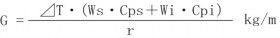
G
:
Amount of created condensate(kg/m)
⊿T
:
Temperature rise as a result of warming-up(℃)
Ws
:
Mass per unit length of pipe material(kg/m)
Wi
:
Mass per unit length of lagging material (kg/m)
Cps
:
Specific heat of pipe material(kJ/kg・℃)
Cpi
:
Specific heat of lagging material (kJ/kg・℃)
r
:
Evaporative latent heat (kJ/kg)
For reference, table 3.1 shows the amount of condensate generated when heating the pipe to the saturation temperature of a given pressure, assuming the pipe temperature before venting is 0°C. (Lagging materials are not considered)
Table 3.1 Amount of created condensate for steam lines
Size
(mm)
Mass
(kg/m)
Pressure (MPaG)
0.06
0.1
0.2
0.4
0.6
0.8
1.0
1.2
1.4
1.6
25
32
40
50
2.57
3.47
4.10
5.44
0.064
0.087
0.103
0.136
0.069
0.093
0.110
0.146
0.078
0.105
0.124
0.165
0.091
0.123
0.145
0.192
0.101
0.136
0.161
0.213
0.109
0.147
0.174
0.230
0.113
0.153
0.181
0.240
0.122
0.165
0.195
0.259
0.128
0.173
0.205
0.272
0.134
0.181
0.214
0.283
65
80
90
100
125
9.12
11.3
13.5
16.0
21.7
0.228
0.283
0.338
0.401
0.544
0.244
0.303
0.362
0.429
0.582
0.276
0.342
0.409
0.485
0.657
0.322
0.399
0.477
0.565
0.767
0.357
0.443
0.529
0.627
0.850
0.386
0.479
0.572
0.678
0.919
0.403
0.499
0.596
0.706
0.958
0.434
0.538
0.643
0.762
1.03
0.456
0.564
0.674
0.799
1.08
0.475
0.589
0.704
0.834
1.13
150
200
250
300
350
400
27.7
42.1
59.2
78.3
94.3
123
0.694
1.05
1.48
1.96
2.36
3.08
0.742
1.13
1.59
2.10
2.53
3.30
0.839
1.28
1.79
2.37
2.86
3.73
0.978
1.49
2.09
2.77
3.33
4.34
1.09
1.65
2.32
3.07
3.69
4.82
1.17
1.78
2.51
3.32
3.99
5.21
1.22
1.86
2.61
3.46
4.16
5.43
1.32
2.01
2.82
3.73
4.49
5.86
1.38
2.10
2.96
3.91
4.71
6.14
1.44
2.19
3.09
4.08
4.91
6.41
Saturated steam temperature(℃)
Evaporated latent heat (kJ/kg)
113.6
2,220
120.4
2,201
133.7
2,163
151.9
2,107
165.0
2,064
175.4
2,029
184.1
1,998
191.7
1,971
198.3
1,945
204.4
1,921
-
The amount of steam required to raise 1 m of piping (Sch40) from 0°C to the saturated steam temperature is shown in kg. The specific heat of steel is assumed to be 0.49 kJ/kg・℃.
-
-
-
Equipment
In the case of equipment, the equipment and heated material or reactive material remaining in the equipment are heated. The amount of created condensate can be calculated from the following formula, based on the total amount of required heat.
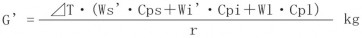
G' : Amount of created condensate (kg)
⊿T : Temperature riseas a result of warming-up (℃)
Ws' : : Total mass of pipe material which constitute the equipment (kg)
Wi' : Total mass of materials other than pipe material which constitute the equipment (kg)
Wl : Total mass of heating target (kg)
Cps : Specific heat of pipe material (kJ/kg・℃)
Cpi : Specific heat of material except pipe material (kJ/kg・℃)
Cpl : Specific heat of heating target (kJ/kg・℃)
r : Evaporated latent heat (kJ/kg) -
-
Steam trace lines
Steam tracing is the process of laying steam lines along oil transport lines to keep the oil at an appropriate temperature to prevent it from solidifying or becoming excessively viscous. In the case of these steam trace lines, it is necessary to consider not only the heating of trace lines, but also heating targets such as oi and other contents (heated material) and its transport line, as well as the insulation and lagging material.. The amount of created condensate can be calculated using the following formula.

G : Amount of created condensate (kg/m)
T1: Temperature risein trace lines (℃) (until saturated temperature of trace steam)
Ws1 : Mass per unit length of trace lines(kg/m)
Ws2 : Mass per unit length of steam main lines (kg/m)
W1' : Mass per unit length of contents in steam main lines (kg/m)
Cps1: Specific heat of trace lines (kJ/kg・℃)
Cps2: Specific heat of steam main lines(kJ/kg・℃)
Cp1': Specific heat of contents in steam main lines (kJ/kg・℃)
⊿T2: : Temperature rise of steam main line, heat insulation, and lagging material(℃) (until operating temperature of contents in main lines)
r : Evaporative latent heat (kJ/kg)In the above cases, we have described how to calculate the amount of condensate, but in order to determine the condensate discharge capacity of a steam trap, the amount of condensate per unit time (kg/h) must be estimated.. The amount of condensate per hour can be determined by determining the appropriate warm-up time referring to “3.1.2 Warm-up time”.">
-
-
Warm-up time
If the wall thickness of the metal parts that make up the equipment is large, the burden caused by the heat (thermal stress) will increase if the heating is rushed.
(Thermal stress) also increases, which may cause internal defects or damage. Therefore, when they are used at relatively high pressures, it is common to spend some time (e.g., several hours) on them because their wall thicknesses are also larger On the other hand, when the equipment works in low pressure and the thickness of materials is decreased, the warm-up time is decreased, and it warms-up quickly.
In this way, the warm-up time depends on the equipment and operating situation. However, depending on the number of stops, and thus the frequency of warm-up, it is roughly as follows
-
● Batch operation : about 15 minutes
-
● Number of times it is stopped
Once per day:within one hour
Once per week:for one or two hours
Once per year:for several hours
However, even if the warm-up time is short, such as in batch operation, if a relatively large amount of condensate remains in the piping or equipment, it is safe to run the steam slowly while gradually increasing the steam amount (for example, over about an hour). This is because water hammer may occur if the steam is run all at once.
-
-
The amount of condensate during normal operation
This section describes the formula for the amount of created condensate around steam main lines and various kinds of equipment.
-
Steam main lines
Heat quantity which diffuses from pipe material or insulation material to the air is different depending on the material, thickness, and air conditions.
The following formula can be used for calculating the amount of condensate created in the pipe due to heat loss.
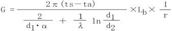
G
:
The amount of created condensate (kg/h)
d1
:
Outside diameter of insulation material (m)
d2
:
Internal diameter of insulation material (m)
λ
:
Thermal conductivity of insulation material (kJ/m・h・℃)
α
:
Surface thermal conductivity (kJ/㎡・h・℃)
ts
:
Steam temperature (℃)
ta
:
Air temperature (℃)
Lb
:
line length (m)
r
:
Evaporation latent heat (kJ/kg)
-
Equipment
-
Dryer (Air heater)
一This is often used as a hot air dryer and is the most commonly used in factories.
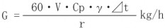
G
V
:
:
Amount of creating condensate(kg/h)
Air mass flow(㎥/min)
Cp
:
Low pressure specific heat in the air(kJ/kg・℃) Cp=1
γ
:
Weight volume ratio in the air(kg/㎥)γ=1.226
⊿t
:
Difference in temperature rise(℃)
r
:
Evaporation latent heat(kJ/kg)
Since it is often difficult to grasp the above calculation conditions for dryers, it is common to use the values obtained by the following method.
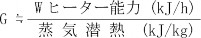
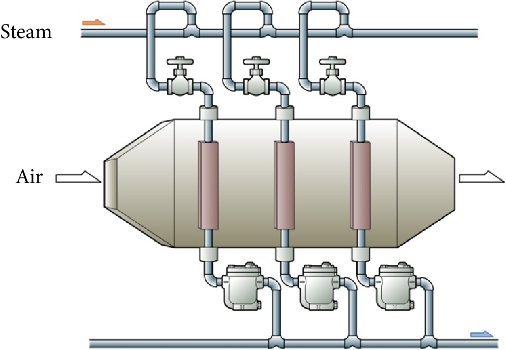
Figure 3.1Air heater
-
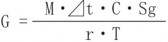
Heat transfer equipment
Heat transfer devices are containers, such as a reboiler or evaporator, that transfers the heat energy of steam to a low-temperature fluid through a heat transfer surface such as a coil. The following simplified formula is usually used to calculate the amount of condensate generated because the calculation process of temperature difference is complicated.
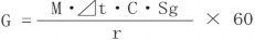
G
M
:
:
Amount of creating condensate(kg/h)
Flow rate of heating materials(ℓ/min)
⊿t
:
Specific heat of heating materials (kJ/kg・℃)
C
:
Specific heat of heating materials (kJ/kg・℃)
Sg
:
Specific gravity of heating materials(kg/ℓ)
r
:
Evaporation latent heat(kJ/kg)
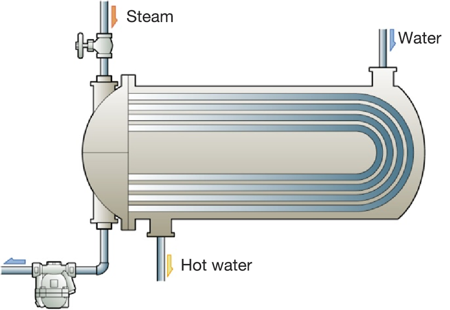
Figure 3.2 Shell and tube heat exchange device
-
Steam jacketed kettle
This is especially used in food factories. They may be fixed type or rotary type.
G
M
:
:
Amount of created condensate(kg/h)
Amount of flow rate of heating materials (ℓ)
⊿t
:
Difference in temperature rise (℃)
C
:
Specific heat of heating materials (kJ/kg・℃)
Sg
:
Specific gravity of heating materials(kg/ℓ)
T
r
:
:
Operating time (h)
Evaporation latent heat(kJ/kg)
-
-
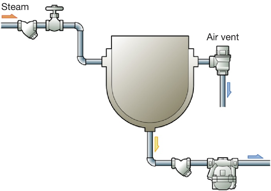
Figure 3.3 Formularized jacketed kettle
-
Press
Steam presses are widely used in rubber, plastic, plywood, and cleaning industries.

G
:
Amount of created condensate(kg/h)
A
:
Contact area with product(㎡)
R
:
Concentration factor(kg/m2・h)
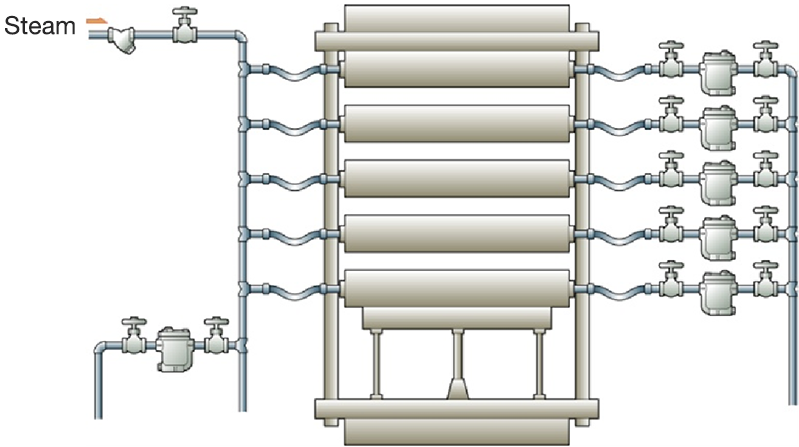
Figure 3.4 Vulcanization press example
-
Autoclave
Autoclave is an equipment that sterilizes, purifies, and dries products directly using increasing steam pressure. It is a pressure container used for medical and kitchen purposes.
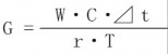
G
W
:
:
Amount of created condensate(kg/h)
Weight of product(kg)
C
:
Specific heat of product(kJ/kg・℃)
⊿t
:
Temperature rise of product(℃)
r
:
Evaporation latent heat(kJ/kg)
T
:
Operating time(h)
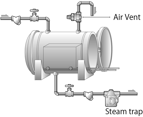
Figure 3.5 Direct-injection Type Autoclave
-
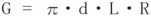
Cylinder dryer
A cylinder dryer is equipment for drying products by bringing them into contact with the outer surface of a cylinder filled with steam. It is generally used a lot in paper, cardboard, and laundry factories. A siphon is often used for discharging condensate except in the case of certain equipment.
G
:
Amount of created condensate(kg/h)
d
:
Cylinder diameter(m)
L
:
cylinder length(m)
R
:
Condensation coefficient(kg/m2・h)
Figure 3.6 Cylinder dryer
-
-
Amount of condensate created in steam trace lines
Steam consumption in steam tracing, or the amount of condensate generated, is determined by the amount of heat dissipated from the piping. MIYAWAKI provides detailed professional advice on the methods of calculation based on the results of joint research with our customers.
-
-
Condensate flow of steam traps
-
-
Basically, when deciding the condensate flow of steam traps, the maximum amount of condensate is estimated based on the condensate flow at warm-up and that of normal operation, and multiply this by the safety ratio (about 2 times). However, the amount of condensate at warm-up is generally larger than that of normal operation. This difference is particularly noticeable in large systems.
Thus, if the condensate flow of steam traps is decided based on the condensate flow at warmup, the determined flow may be over capacity for normal operation. This should be determined with warm-up time in mind. However, if the warm-up time is likely to be long with only a steam trap, it is wise to install a bypass valve exclusively for the warm-up time and select a steam trap according to the steady-state condensate volume.
In addition, the pressure is very low at warm-up and condensate flow of steam traps may be small. This point should be considered when selecting steam traps.