-
Function and Operation of Steam Traps
-
Operating Principles of Steam Traps
-
-
-
This section describes the design and operating principles of each type of steam trap.
-
Bucket Traps
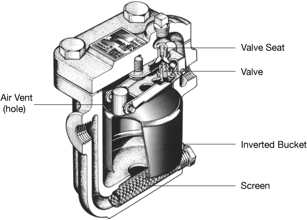
Figure 2.1 Inverted Bucket Trap
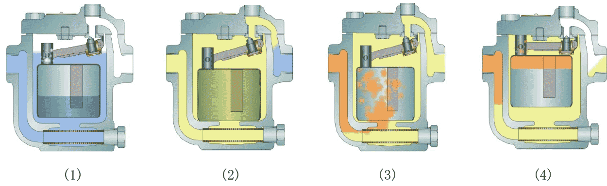
Figure 2.2 Operation of Bucket Trap
-
1) At the beginning of steam venting, low temperature condensate and air enter the steam trap. At that time, the bucket is positioned at the bottom of trap and the valve is fully open. Condensate will quickly discharge from the valve, and air will discharge through the air vent.
-
-
2) After the line warms up, the discharged condensate temperature is gradually raised.
-
3) After the condensate, steam flows into the steam trap and occupies space in the bucket. The bucket will get buoyancy.
-
-
4) The bucket will flat upward after it is given enough buoyancy, and the valve will close.
The condensate flows back in the trap, steam in the bucket discharge s through the air vent, and condensate fills the bucket. The bucket will lose its buoyancy and sink, and then open again. The valve opening/closing procedure is repeated.
-
-
Ball Float Traps (lever-type)
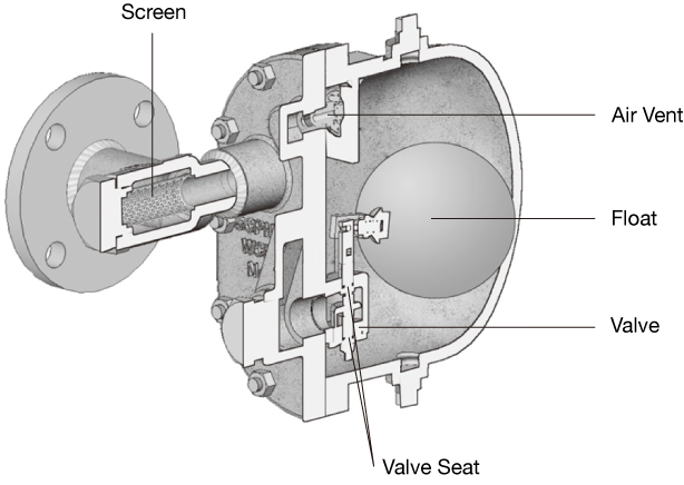
Figure 2.3 Ball Float Trap (double ported balance valve system)
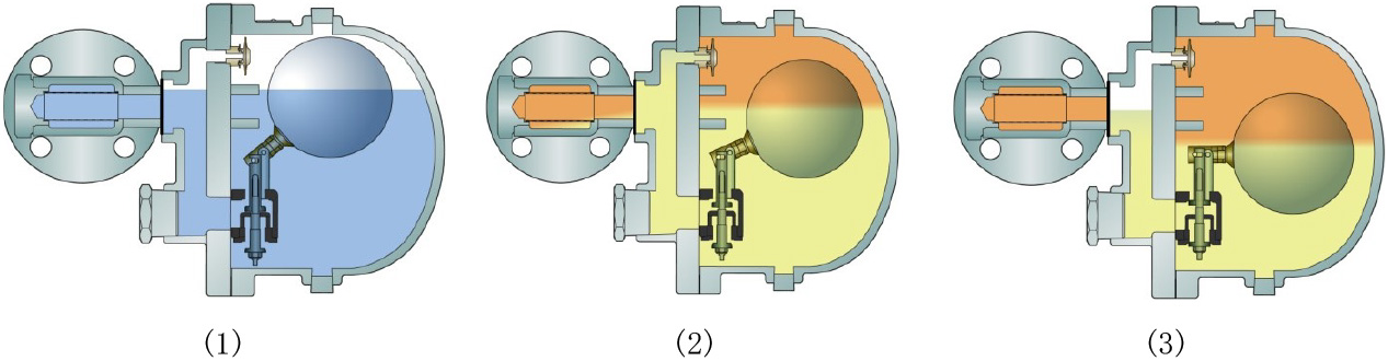
Figure 2.4 Operating principles of ball float trap
-
(1) At the beginning of steam venting, air is quickly discharged through the thermostatic air vent which is located at the upper side of the trap and is fully open. At the same time, cold condensate gradually fills the trap, and the ball floats up significantly
-
-
(2) The buoyancy is added to the valve through the lever, and the valve located at the bottom of trap is fully open to drain condensate.
-
When condensate temperature continues to rise, initial air is fully discharged. Then, the air vent closes and high temperature condensate continues to discharge only through the valve in the bottom of trap. After that the high temperature condensate and steam enters the trap.
-
-
(3) When the amount of condensate decreases, the float moves up and down in accordance with the amount of condensate, and condensate is discharged continuously by adjusting the valve opening degree.
-
-
Ball Float Traps (lever-free type)
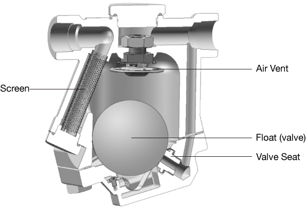
Figure 2.5 Ball Float Trap (lever-free type)
Figure 2.5 shows the lever-free ball float trap. The difference with the ball float trap with lever is that the float simultaneously functions as a valve. The operating principle is the same as that of ball float with lever.
-
Thermostatic Traps
-
Temperature Control Traps
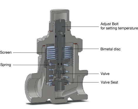
Figure 2.6 Temperature Control Trap
Figure 2.7 Operating principles of temperature control trap
-
(1) At the beginning of steam venting, bimetal discs are all flat and the valve shaft is pushed up by a spring. As a result, the valve is fully open and cold condensate and air in the steam line are rapidly discharged.
-
-
(2) As the temperature of condensate increases, the bimetal disc begins to curve and forces the valve shaft to move down against the upward force of spring. The valve gradually closes. When the temperature of condensate increases and approaches to the setting temperature, the bimetal disc curves more and the valve is only slightly open.
-
-
(3) When the temperature of condensate reaches the set temperature, then the valve is fully closed.
From here, the operating state (2) is maintained, or cycle (2) to (4) is repeated.
-
-
-
Diaphragm-type Traps
*The diaphragm thermo is the name of the diaphragm trap thermoelement manufactured by Miyawaki
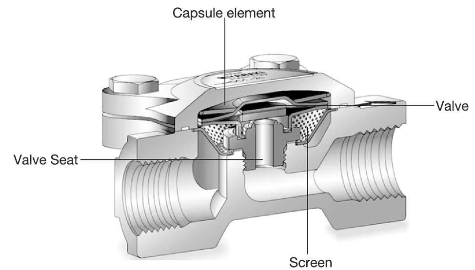
Figure 2.8 Diaphragm Steam Trap
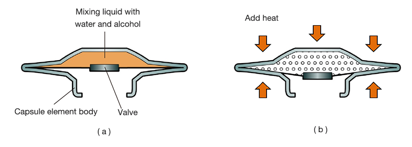
Figure 2.9 Thermosensor element (Diathermo)
As shown in Figure 2.9, the diathermo thermosensor element is a metal capsule filled with a mixture of water and alcohol whose saturated temperature is slightly lower than that of water. At low temperatures, the enclosed liquid is in a liquid state (a), but at high temperatures, it evaporates and expands, pushing down the bottom surface that makes up the valve (b). It condenses again at low temperatures, and it returns again to state (a). The valve opens and closes by expansion and constriction.
The difference of saturated temperature between water and the mixed-in liquid remains almost constant against changing pressure. Thus, no matter what the pressure, the valve will open in a stable temperature lower than that of saturated steam temperature.
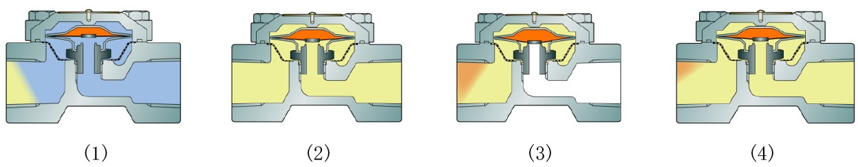
Figure 2.10 Operating principle of Diaphragm Type Trap
-
(1) At the beginning of steam venting, the valve is fully open and cold condensate and air are discharged quickly.
-
-
(2) When the condensate temperature increases, the capsule element starts to expand and the valve becomes closing.
-
-
(3) As the condensate temperature increases, the diathermo expands to close the valve.
-
-
(4) Eventually, as the condensate temperature become low due to heat release, the pressure within the diathermo starts to decrease. Then, as the pressure becomes lower than ambient pressure, the valve will open again.
-
During normal operation, (3) and (4) will repeat continuously.
-
-
Thermodynamic Traps
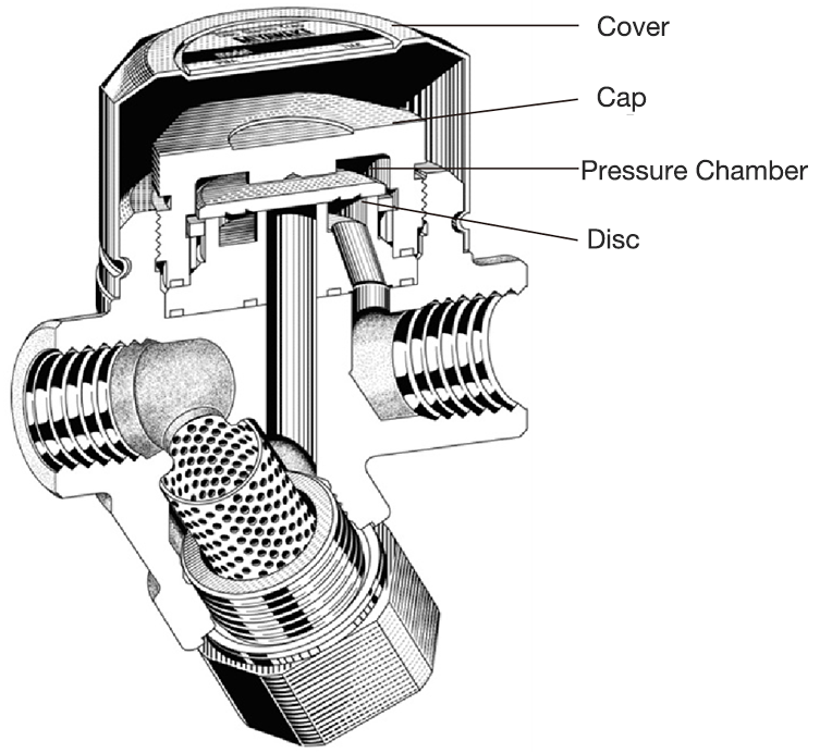
Figure 2.11 Thermodynamic Disc Trap
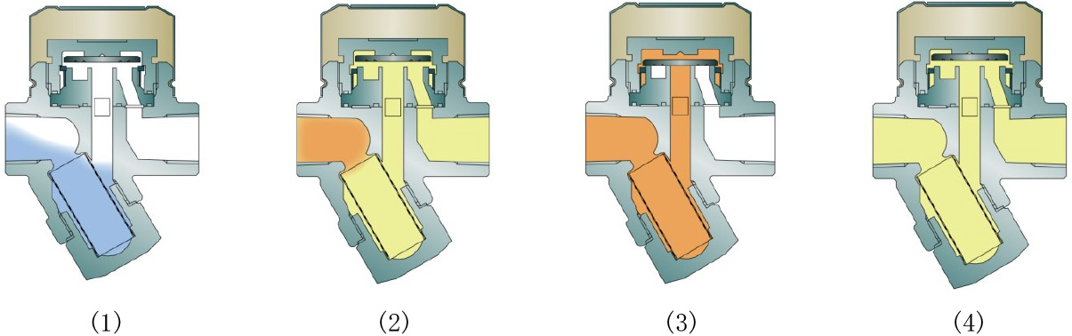
Figure 2.12 Operating Principles of Thermodynamic Disc Trap
-
(1) At the beginning of steam venting, primary side pressure pushes up the disc from the bottom, and cold condensate and air are discharged quickly.
-
-
(2) Eventually, after hot condensate flows into the trap, steam enters.
-
(3) As hot condensate passes between the disc and the disc seat, flash steam is generated and fills the pressure chamber along with some condensate. As a result, the pressure of the chamber and the upper pressure of the disc increase. Additionally, the pressure on the underside of the disc drops as the high-speed steam passes through, causing the valve to close.
-
-
(4) When the condensate enters the trap again, the transformer steam will remain closed until the steam in the pressure chamber condenses due to heat radiation, but eventually condenses and its pressure drops. The pressure on the lower side of the disc overcomes the pressure on the upper side of the disc to open the valve.
-
-
-
The opening and closing of the valve then repeats continuously
The pressure relationship related to the opening and closing operation is as follows.
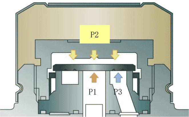
The primary pressure, the pressure of pressure chamber, and secondary pressure of thermodynamic disc trap relate to P1, P2 and P3 and the areas on which the disc is pressured relate to A1, A2 and A3.
Figure 2.13 Pressure relationship related to opening and closing operation
As shown in Figure 2.13, primary pressure and secondary pressure contribute to valve opening force, and the magnitude of the force is P1×A1 and P3×A3, respectively. On the other hand, the pressure in the pressure chamber contributes to the closing force, and its magnitude is P2 × A2.
Thus, the valve will open and close when the force applied to the disc acts in relation to the following formula.
Valve opening :P1×A1+P3×A3>P2×A2
Valve closing :P1×A1+P3×A3<P2×A2
As described when explaining the operation, the opening force relationship is established at the start of steam venting when there is no pressure in the pressure chamber, or the pressure in the pressure chamber decreases due to steam condensation. The force relation of valve closing described above holds when the pressure on the underside of the disc is reduced due to the passage of high-speed steam, and then while the pressure in the pressure chamber exceeds the pushing force by the primary and secondary pressures.